
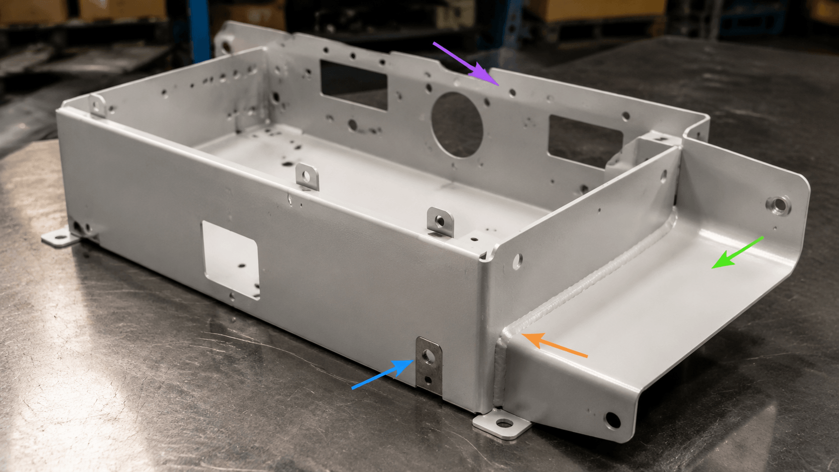
Direct answer: “Metal powder coated” usually means a fabricated metal part with a dry powder finish applied electrostatically to its prepared surface, then melted and heat-cured. It describes a surface treatment, not a component made from loose metal powder. For an OEM part that also includes high precision machining services, the machining dimensions and the coating requirements need separate callouts but coordinated process planning.
A note such as “powder coated black” is rarely enough for an RFQ. The drawing or purchase specification should identify the substrate, preparation expectations, coating system, color, gloss, texture, film requirement, appearance zones, masking limits, functional interfaces, and inspection basis. This guide applies to custom sheet metal parts, enclosures, cabinets, brackets, frames, and welded assemblies, including products that combine fabrication, CNC machining, finishing, and assembly.
What “Metal Powder Coated” Means for an OEM Part
When a buyer releases a formed enclosure, welded frame, bracket, cabinet, or machined-and-fabricated assembly, “metal powder coated” normally identifies the finish applied after the required fabrication and machining work. The base part remains the specified metal, while the powder forms a cured film on prepared surfaces reached by the application process.
- Powder-coated metal: the base part remains steel, galvanized steel, stainless steel, aluminum, or another compatible metal. The powder is the finish.
- Powder metallurgy: a separate manufacturing route that compacts and processes metal powder to make a component. It is not the meaning of powder-coated metal.
- Liquid paint: a wet coating applied and dried or cured through a different route.
- Electroplating and galvanizing: metal-deposition processes rather than paint-like powder films.
- Anodizing: a substrate-conversion process commonly associated with aluminum, not a powder film applied over the part.
These processes may produce related appearance or performance goals, but they are not interchangeable. The choice affects substrate preparation, geometry, masking, dimensional change, application access, curing, and inspection.
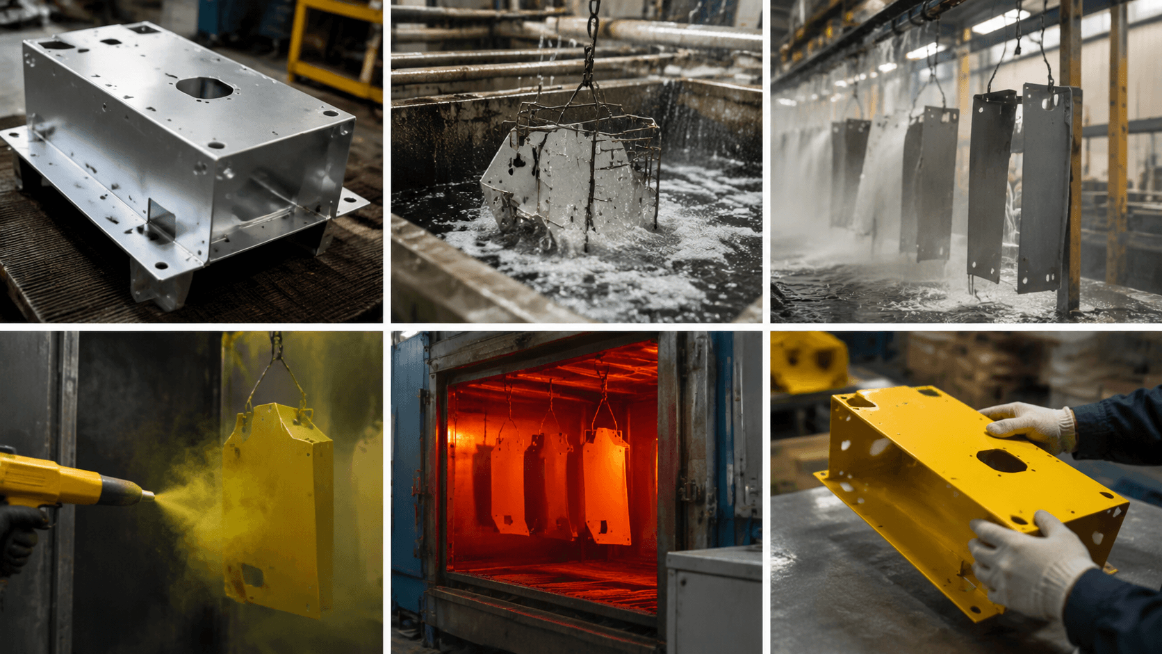
The Route from Fabricated Part to Finished Surface
Powder coating should be considered while the fabrication and machining sequence is planned, not treated as an isolated color operation at the end. A coated cabinet or welded frame can show problems caused by burrs, weld spatter, residue, rough transitions, or undefined contact surfaces.
- Fabrication and machining: complete the required cutting, punching, bending, welding, turning, milling, drilling, or other operations. Identify critical dimensions and interfaces that must remain functional after finishing.
- Weld and surface condition: address specified burrs, spatter, sharp transitions, visible residue, and weld appearance before the finishing route begins.
- Cleaning and preparation: address oil, dirt, rust, oxide, weld residue, or other contamination. The route depends on the substrate, contamination, selected powder system, and required performance; there is no fixed preparation recipe for every part.
- Powder application: apply the selected dry powder electrostatically. Recesses, internal corners, narrow cavities, edges, and fixture contact points may not receive the same coverage as open faces.
- Curing: heat the applied powder according to the selected system’s cure window and the project requirement. Temperature and time must be tied to that system rather than treated as universal settings.
- Inspection: review appearance, color, gloss, texture, film build, masked areas, and functional interfaces against agreed acceptance methods.
Bare steel, galvanized steel, stainless steel, and aluminum can present different oxide, zinc, contamination, or surface conditions and may require different preparation decisions. Burrs, sharp edges, weld spatter, rough transitions, and residue can influence adhesion, corrosion resistance, edge coverage, and visible uniformity. The final preparation and cure window should be confirmed against the selected powder system and project environment.
For adjacent process options, review surface-finishing options for custom metal parts.
Coordinating Machined Interfaces with the Coating
Machining and coating are distinct manufacturing scopes, but they must be planned together where the finish can affect fit or function. A buyer requesting high precision machining services for an insert, mounting feature, bracket, or enclosure interface should identify which dimensions are measured before coating, which must remain available after coating, and which surfaces require masking or controlled coverage.
- Precision holes and bores: identify reamed holes, bearing seats, dowel locations, and other fit-critical features that could lose clearance if coated.
- Threads: state whether tapped holes must remain uncoated, whether controlled residual film is acceptable, and how fastener engagement will be checked.
- Press fits and mating faces: mark insertion areas, sliding surfaces, flanges, gasket seats, door overlaps, and other interfaces where film build could interfere with assembly.
- Machined reference surfaces: distinguish datum, locating, sealing, and contact surfaces from cosmetic surfaces. The drawing should assign responsibility for dimensional and functional inspection.
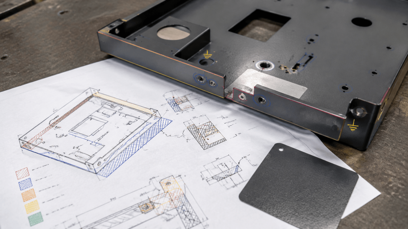
- Grounding points: mark grounding pads, bonding points, and electrical contact surfaces for masking or an agreed post-coating treatment. State any required continuity or contact check.
This does not mean machining and coating should be described by one blended note. Their requirements remain separate: machining controls the part geometry and interfaces, while coating controls the selected surface finish and its coverage. Coordinated planning prevents the finished coating from invalidating a previously acceptable machined or fabricated feature.
Specification Fields That Prevent Ambiguity
At the RFQ stage, the finish note must give the supplier enough information to plan fabrication, machining interfaces, masking, coating, and inspection together. If a cabinet, bracket, or welded assembly is released only as “powder coated black,” quotation assumptions may differ from the buyer’s expectations for appearance, fit, and functional coverage.
| Specification field | What to define |
|---|---|
| Substrate and condition | Metal type, grade where relevant, material thickness, welded condition, and any galvanized or pre-finished surface. |
| Coating system | Selected powder system, approved finish reference, or supplier data. Confirm compatibility with the substrate and service environment. |
| Color and appearance | Color reference or approved physical sample, gloss level, texture, and the surfaces where appearance is critical. |
| Film and cure | Target film thickness or a supplier-defined requirement, with cure requirements tied to the selected powder system. Do not insert a universal value. |
| Environment | Indoor or outdoor exposure, moisture, chemicals, UV, temperature, cleaning agents, and other conditions relevant to finish selection. |
| Appearance and masking zones | Critical visible faces, concealed areas, acceptable fixture marks, no-coat areas, and controlled-coat areas for functional interfaces. |
| Machining and dimensional interfaces | Critical tolerances, threads, precision holes, press fits, mating faces, datums, and whether dimensions apply before coating, after coating, or at both stages. |
| Inspection basis | Visual review, color, gloss, texture, film thickness, sample comparison, functional fit, and any cure or adhesion verification, with methods and acceptance criteria agreed for the project. |
| Supply condition | Required quantity, batch separation, packaging, delivery form, and whether the part is supplied coated, assembled, or both. |
Masking complexity, part dimensions, batch separation, rework, and curing constraints can affect process planning. State these factors early, along with critical dimensional tolerances and interfaces, rather than leaving them to interpretation after fabrication.
Metal Powder Coated Specification Checklist: From Material and Masking to Sample Approval
- Attach the current 2D drawing, critical tolerances, 3D file, and revision level.
- Identify the material, thickness, surface condition, weld condition, and any machined interfaces.
- Provide the coating-system reference, color sample or code, gloss, texture, and appearance zones.
- Describe the service environment and any required performance checks.
- Mark threads, precision holes, grounding points, press fits, mating faces, labels, drains, and other masking limits.
- State the film, cure, inspection, quantity, delivery, packaging, and batch requirements.
- Define whether a first article or physical finish sample must be approved before batch production.
Specification review: For quotation or prototype review, provide the drawings, critical tolerances, material and thickness, finish reference, environment, masking requirements, prototype quantity, and expected batch volume. Yishang can review powder-coated requirements alongside custom sheet metal fabrication before the production scope is finalized.
Design Callouts for Fit, Grounding, and Assembly
A coating that looks acceptable on an enclosure can still prevent a fastener from engaging, reduce clearance at a machined interface, interrupt electrical contact, or affect a gasket face. Drawings should distinguish cosmetic surfaces from functional surfaces and state where coating is required, controlled, or prohibited.
- Threads and tapped holes: state whether each thread must remain uncoated, whether controlled residual film is acceptable, and how fastener engagement will be checked.
- Precision holes and press fits: identify bearing seats, reamed holes, inserts, and press-fit areas. If a machined component mates with sheet metal, define the interface and inspection responsibility for both parts.
- Grounding and electrical contacts: mark grounding pads, bonding points, and contact surfaces for masking or an agreed post-coating treatment. State any required continuity or contact check.
- Mating faces and seals: identify flanges, gasket seats, sliding areas, door overlaps, and other interfaces that need controlled coating or no coating.
- Labels and markings: reserve areas for labels, barcodes, nameplates, or adhesive features where texture and film build could affect attachment or readability.
- Edges, folds, cavities, and drains: define critical edge appearance, internal access, drain paths, and acceptable hanging or fixture locations. Weld seams and transitions may need separate appearance callouts.
For example, a metal enclosure may have a visible door face, an uncoated grounding pad, masked fastener holes, and a controlled mating flange. Those areas should not be covered by one general “coat all surfaces” note because cosmetic coverage and functional coverage have different acceptance needs. Buyers can also review enclosure applications where coating, masking, and fit work together.
Choosing Among Powder Coating and Other Finishes
A finish should be selected against the complete part requirement, especially when an assembly includes close-tolerance machined features, inaccessible recesses, heat-sensitive components, or a defined exposure environment. Compare the substrate, geometry, appearance, quantity, part dimensions, curing constraints, masking effort, and required function rather than choosing by color alone.
| Process | Process identity | Points to confirm |
|---|---|---|
| Powder coating | Dry powder is electrostatically applied and heat-cured into a film. | Substrate preparation, powder compatibility, curing route, access to recesses, masking, film build, and assembly clearance. |
| Liquid paint | A wet coating is applied and then dried or cured through a separate route. | Paint-system compatibility, application and drying controls, film build, appearance, and environmental suitability. |
| Electroplating | A metal layer is deposited through an electrochemical process. | Base-metal compatibility, contact or rack marks, recess coverage, deposited thickness, electrical or wear requirements, and dimensional effects. |
| Anodizing | A substrate-conversion process commonly associated with aluminum rather than a paint-like powder film. | Aluminum alloy, color and sealing requirements, surface appearance, and dimensional effects on formed or machined areas. |
| Galvanizing | A zinc-coating route generally selected for steel applications. | Selected galvanizing method, geometry, drain or vent needs where applicable, threaded areas, dimensional effects, and intended exposure. |
For example, a welded steel frame may be considered for powder coating when its preparation, access, dimensions, and curing route are suitable. A heat-sensitive feature, inaccessible recess, or required deposited-metal function may point to another process. The final choice should follow the complete part and assembly requirement.
Release Inspection for Coated Parts
Before a prototype or production batch is released, inspection should verify more than general visual appearance. A coated part may match the expected color but still fail at a thread, precision hole, grounding point, seal, or mating face. Review should connect the approved finish reference with dimensional and functional requirements.
- Confirm identity: check the drawing revision, material, batch, coating reference, critical dimensions, and supply condition.
- Review appearance: look for runs, contamination, pinholes, exposed substrate, uneven texture, poor edge coverage, and fixture marks in defined appearance zones.
- Compare the finish: compare color, gloss, and texture with the approved sample or reference using the agreed review method.
- Check film thickness: measure where required using a method suitable for the substrate and coating system, with no assumed universal pass limit.
- Verify cure or adhesion: perform these checks only when the project specifies an appropriate method and acceptance criterion.
- Verify function: check masked threads, holes, grounding faces, mating surfaces, labels, seals, and enclosure fit.
- Release the batch: record sample comparison, nonconformities, rework decisions, batch identification, and required inspection documentation.
First-article or approved-sample review is useful when color, texture, masking, machined interfaces, and assembly fit interact. It establishes a shared baseline before batch comparison, while the project specification determines which tests and acceptance limits apply. Buyers can also review quality-control considerations for coated metal products.
Request a fabrication and finish review: Share the current 2D drawings and 3D files, revision, critical tolerances, material and thickness, machined interfaces, color reference or approved sample, gloss and texture, service environment, masking and grounding requirements, prototype quantity, expected batch volume, delivery form, and inspection criteria. Yishang can review the fabrication route, coating specification, masking needs, and assembly risks for custom sheet metal parts, enclosures, cabinets, frames, brackets, and welded assemblies before quotation or prototype approval.
Frequently Asked Questions
What laser cutting precision details should buyers define before requesting a quote?
Buyers should define the functional requirement, drawing notes, critical dimensions, material or process expectations, and any inspection points related to laser cutting precision. This helps suppliers quote the same manufacturing scope instead of making different assumptions.
How can cut hole locations affect cost, fit, or lead time?
cut hole locations can change tooling, forming, welding, finishing, inspection, or rework requirements. If buyers do not clarify it early, two supplier quotes may look comparable while covering different production risks.
Why should bend-to-hole dimensions be reviewed before prototype approval?
bend-to-hole dimensions may look acceptable on a single sample but become harder to control during batch production. Buyers should confirm whether the prototype reflects the same process, finish, and inspection conditions expected for production.
What inspection points matter most for high precision machining services projects?
Important inspection points usually include fit-critical dimensions, holes or mating areas, cosmetic surfaces, finish build-up, welded or formed features, and any dimensions that affect downstream assembly. These points should appear in the RFQ or drawing notes.
How can buyers reduce batch consistency risk before batch production?
Buyers can reduce risk by clarifying drawings, locking key material and finish assumptions, defining inspection timing, approving a representative sample, and confirming which dimensions or surfaces require tighter process control.
How can Yishang help review high precision machining services requirements?
Yishang can review drawings, RFQ notes, material requirements, tolerance expectations, finish details, samples, and assembly needs to identify unclear assumptions before quoting or batch production.