
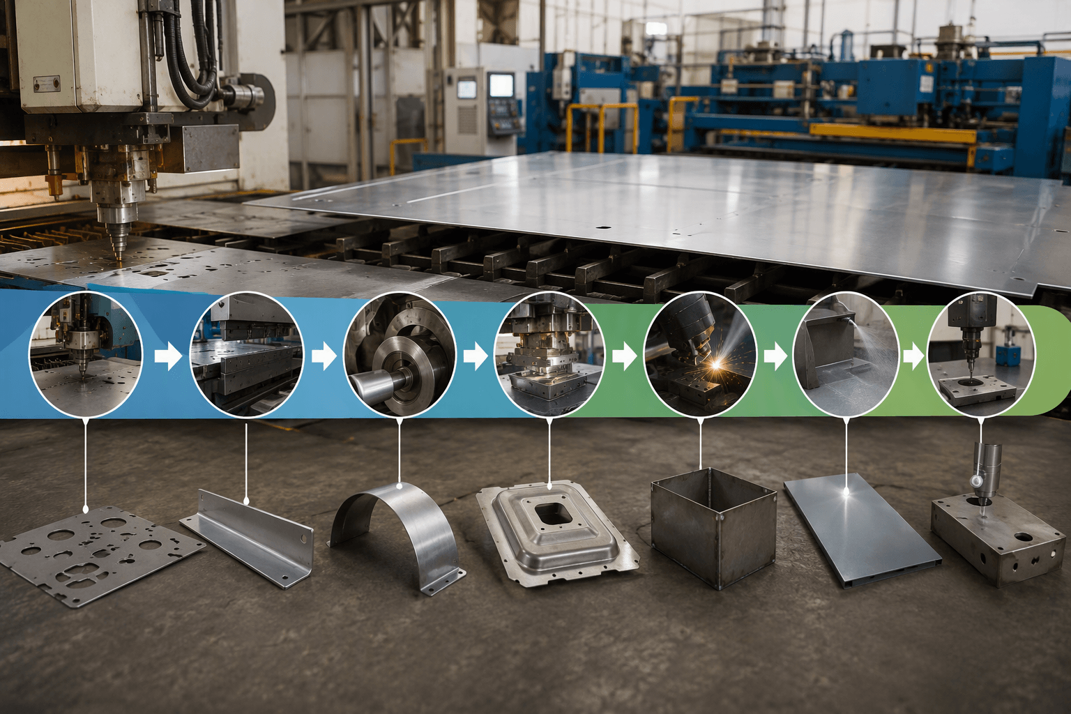
Sheet metal fabrication processes combine cutting or blanking, forming, and—when required—separate joining, finishing, assembly, and inspection steps. The correct route depends on the part’s geometry, material, thickness, tolerances, production quantity, surface requirements, and the secondary operations that follow.
Quick answer: A typical route moves from flat sheet to a cut blank, then to a bent, rolled, stamped, or drawn shape. Welding, mechanical fastening, finishing, assembly, and inspection may follow, but they are downstream operations rather than interchangeable forming processes.
Separate primary and downstream fabrication operations
Sheet metal fabrication is not one operation. The useful distinction is what happens to the material: cutting and blanking separate material, forming reshapes it, joining connects separate pieces, finishing changes or prepares the surface, and inspection verifies the result.
- Prepare stock: select flat sheet and establish orientation.
- Cut or blank: create the perimeter, openings, or blank.
- Form: bend, roll, stamp, draw, or stretch the sheet.
- Join: weld, rivet, screw, bolt, or clinch components.
- Finish: deburr, clean, coat, plate, or otherwise treat the surface.
- Assemble and inspect: confirm fit, function, dimensions, and visible condition.
One part can use several families in sequence. For example, a bracket may be laser cut, press-brake bent, welded, finished, and inspected. A repeated component may instead be produced in progressive tooling, with blanking, punching, forming, and trimming distributed across die stations.
Choosing how to prepare the blank, profile, or holes
Begin by asking whether the required output is a straight cut, a closed blank, an irregular profile, or an opening in otherwise retained sheet.
| Process | Typical role | Selection checks |
|---|---|---|
| Shearing | Straight cuts, strips, and panel sizing. | Blade clearance, burrs, edge condition, and straightness. |
| Laser cutting | Irregular 2D profiles, holes, and openings. | Flexible geometry, heat-affected edges, dross, and deburring. |
| Blanking | Separating a closed outline; the cut blank is retained. | Die design, scrap layout, repeat quantity, and tooling investment. |
| Punching | Holes, slots, notches, and perforation patterns. | Slug removal, burr direction, hole spacing, tool marks, and distortion. |
Blanking and punching are both press-and-die separation operations, but the retained material differs. In blanking, the separated outline is normally the product; in punching, the sheet remains the product and the slug becomes waste. Stamping is a broader press-and-die family that may include blanking, piercing, bending, embossing, and forming, so a punched feature can be part of a stamped component without making punching and stamping synonyms.
Reshaping flat sheet into bends, curves, profiles, and cavities
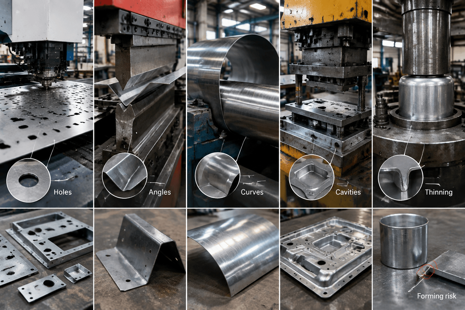
Forming primarily reshapes sheet without deliberately removing material, although some press-and-die stamping sequences combine forming with cutting. Alloy, thickness, grain direction, bend radius, tooling, and lubrication or surface condition can affect springback, stretching, thinning, and cracking.
- Punching: a tool penetrates the sheet and removes a slug.
- Press-brake bending: a tool creates a linear angle or flange.
- Rolling: rollers change curvature incrementally.
- Stamping: a press and die cut or form a component.
- Deep drawing: a blank flows into a die to create a cavity.
Bending for angles and flanges
Press-brake bending is suited to brackets, channels, panels, and enclosures with defined bend lines. The inside radius, flange length, hole-to-bend distance, and bend sequence must suit the sheet and tooling. Springback can change the final angle, so critical bends require a controlled forming plan and inspection method.
Rolling for gradual curves and profiles
Rolling passes sheet through rollers that change its shape incrementally. It is useful for cylindrical, conical, or long curved geometry; roll forming can produce a repeated profile through successive roller stands. Rolling is not the same as progressive tooling, where a strip advances through separate die stations.
Stamping and progressive tooling for repeated operations
Stamping uses a press and die to create a shaped component and may combine cutting with bending, embossing, or shallow forming. Progressive tooling is a specific tooling arrangement: the strip moves through multiple stations, with each station performing part of the sequence. This can support repeat production, but dedicated tool development, material utilization, feed control, change management, and cycle time must be weighed against the expected quantity.
Drawing, deep drawing, and stretch forming
In sheet metal, drawing generally pulls a blank into a die to create walls or a cup-like shape. Deep drawing is a more specific sheet-forming operation for producing a relatively deep cavity, with material flowing into the die and possible stretching or thinning at the walls and corners. Draw depth, corner radii, blank-holder control, and material flow determine whether one or several forming stages are appropriate. Excessive thinning can lead to rupture.
Cold drawing is not automatically the same as deep drawing. The term commonly describes pulling wire, bar, or tube through a die in a cold state; in sheet work, a supplier may use cold drawing or cold forming to describe room-temperature deformation. Confirm the intended operation rather than treating the terms as interchangeable. Stretch forming is different again: the sheet is clamped and stretched over a die to create broad, smooth contours, with controlled tensile stretching rather than primarily drawing material inward.
What happens after cutting or forming?
Downstream operations make a fabricated part usable, presentable, and verifiable, but they should remain separate in the process plan.
Welding versus mechanical joining
Welding uses heat, pressure, or both to create a joint between parts. Heat input, weld sequence, access, and fixturing can affect distortion and assembly fit. Mechanical joining uses bolts, screws, rivets, clinching, or inserts without melting the parent sheet. It may simplify service access, but fastener holes, stack-up, clearances, and hardware installation must be designed early.
Finishing for surface and service requirements
Finishing can include deburring, cleaning, powder coating, painting, plating, anodizing, passivation, or another specified treatment, depending on the material and application. Select it by required appearance, corrosion considerations, handling, masking, and service environment. Visible laser heat effects, punch marks, scratches, weld discoloration, and coating coverage should be discussed before production.
Assembly as a fit-and-function stage
Assembly may involve hardware insertion, subcomponent joining, seals, brackets, or functional fit checks. A part can be dimensionally correct yet fail assembly because of distortion, accumulated tolerances, inaccessible fasteners, or an incorrect joining sequence.
Inspection as verification
Inspection may cover overall dimensions, angles, hole locations, flatness, formed depth, joint condition, and visible finish. Common defect categories include burrs, scratches, distortion, incomplete joints, poor fit, forming cracks, and inconsistent surface treatment. If a part needs tapped holes, machined datum faces, or another precision interface, CNC machining, turning, or milling may be a secondary machining operation rather than a sheet metal forming process.
A formed bracket may follow a cut-then-bend route before joining; see custom metal brackets built to your drawings. An enclosure commonly combines cut panels, bends, finishing, and assembly; see custom sheet metal enclosures that arrive ready to assemble.
Choose the process by geometry, material, volume, and finish
The matrix below is a starting point, not a universal rule. The final route depends on the drawing, material specification, tolerance scheme, and supplier’s review of sequence and tooling.
| Part requirement | Likely route | Questions to resolve |
|---|---|---|
| Flat bracket with holes | Laser cutting or punching/blanking, then bending. | Hole-to-bend distance, burr direction, bend order, and repeat quantity. |
| Bent enclosure | Cutting and press-brake bending, followed by welding or fastening and finishing. | Panel fit, bend sequence, visible surfaces, flatness, and masking. |
| Rolled profile or long curve | Rolling or roll forming, with trimming and end joining if required. | Uniformity of the section, curvature, length, tooling, and handling. |
| Deep cavity or cup | Deep drawing, followed by trimming, piercing, or secondary forming. | Material flow, thinning, corner radius, draw stages, and rupture risk. |
| Repeated formed component | Stamping or progressive tooling when dedicated tooling is justified. | Tool ownership, strip utilization, cycle time, inspection, and design changes. |
For low-volume or frequently changing designs, flexible cutting and press-brake tooling may avoid unnecessary dedicated-tool investment. As quantity increases, blanking, stamping, or progressive tooling can be evaluated when repeatability and cycle time justify the tooling plan. There are no reliable universal volume cutoffs; geometry, material, tolerance, and change frequency can reverse the preferred route.
Material and thickness influence bend radius, springback, draw behavior, thinning, rupture risk, and tool loading. Tighter tolerances may require a more controlled sequence or a distinct machining interface. Compare setup time, cycle time, material utilization, scrap, tooling cost, inspection effort, and secondary deburring, joining, finishing, and assembly—not only the nominal forming operation.
Before finalizing the design, ask the supplier engineer:
- Which dimensions, holes, angles, and surfaces are genuinely critical?
- Can the proposed bend or draw sequence produce the geometry without clashes or cracks?
- Should holes be made before or after forming, and where should inspection datums be located?
- What prototype route is practical, and how would the production route change with quantity?
- Who owns, maintains, and approves any dedicated tooling?
For an early B2B OEM or ODM process-route review, provide the part drawing or 3D model, material and sheet thickness, target production quantity, critical dimensions and tolerances, required finish, and assembly conditions. Request a route review from Yishang to identify likely tooling, forming, joining, finishing, and inspection considerations before production planning.
Frequently Asked Questions
What is the difference between punching and stamping?
Punching removes slugs to create holes, slots, or perforations. Stamping is the broader press-and-die family and can include punching, blanking, bending, embossing, and forming.
Are deep drawing and cold drawing the same sheet metal process?
No. Deep drawing forms a sheet blank into a cavity. Cold drawing commonly refers to pulling wire, bar, or tube through a die without heating it, so the terms should not be used interchangeably.
Which sheet metal process is suitable for low-volume versus high-volume production?
Low-volume work often benefits from flexible cutting and bending, while higher-volume work may justify stamping or progressive tooling. Geometry, tolerance, material utilization, and design stability matter more than a fixed quantity threshold.
Do welding, finishing, assembly, and inspection count as sheet metal fabrication processes?
They may be included in the overall fabrication project, but they are separate downstream operations. Welding joins, finishing treats the surface, assembly combines parts, and inspection verifies the result.