
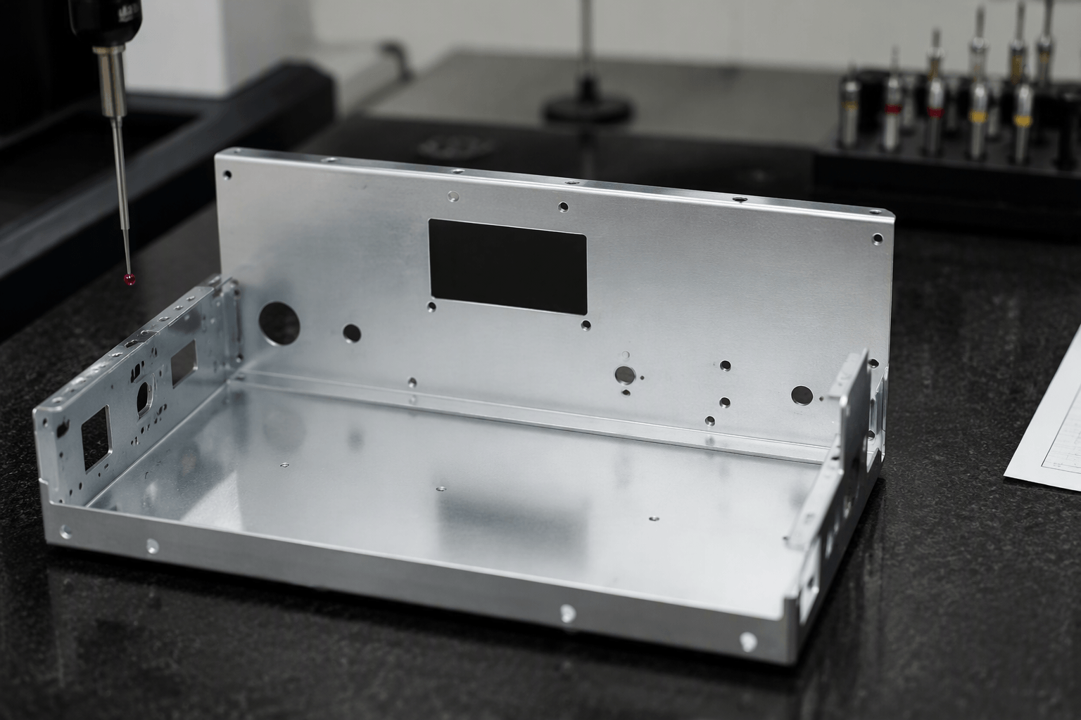
Precision sheet metal fabricators produce cut, formed, joined, and finished sheet components to drawing-defined requirements. Precision does not mean that every material, geometry, process, or production quantity will produce the same result. It means the fabricator selects and controls suitable processes, identifies the dimensions that matter, and verifies the finished part against agreed requirements.
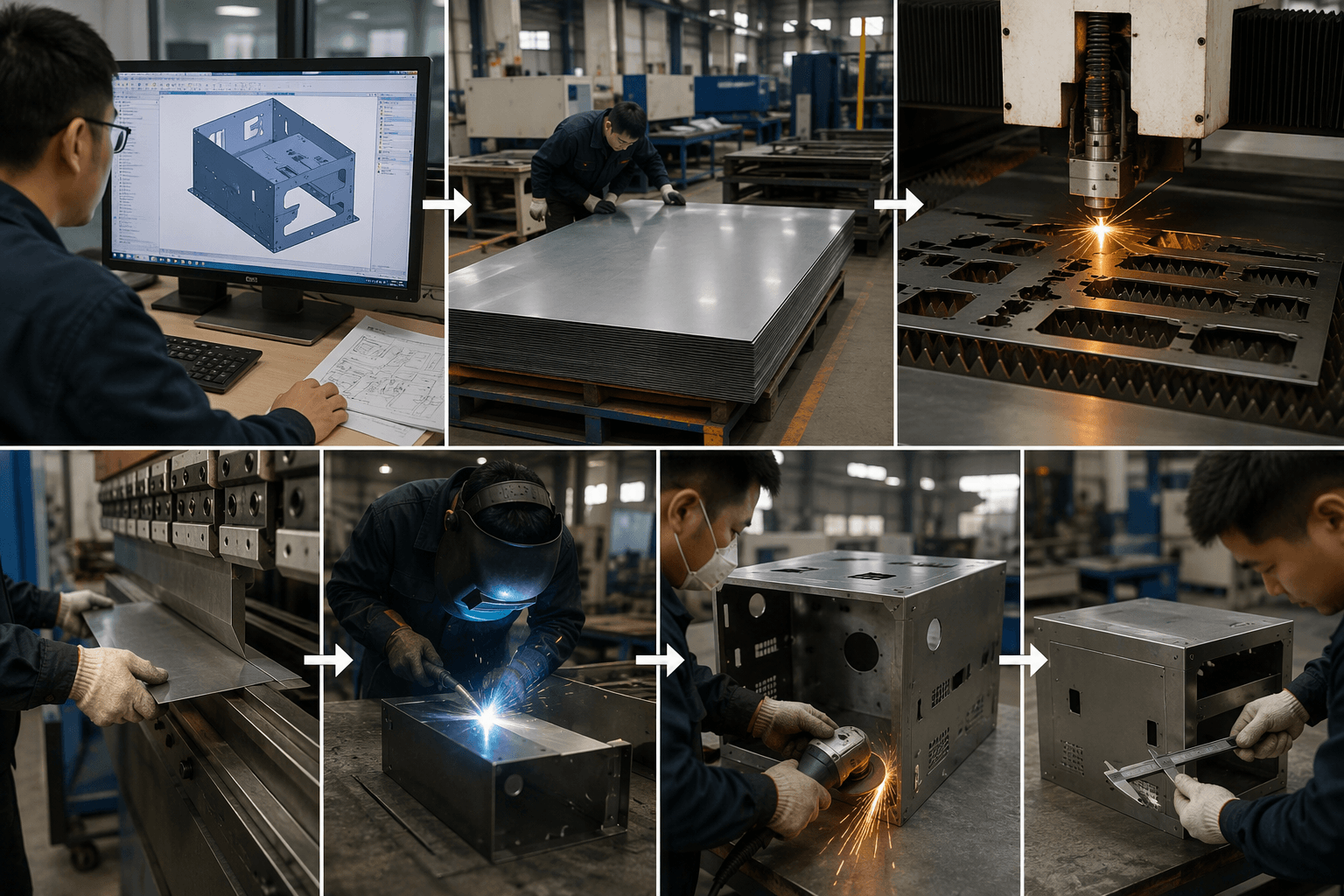
The practical decisions begin before cutting: CAD data and drawings must be interpreted correctly, material and thickness must be confirmed, bend and hole features must be manufacturable, and tolerances must reflect the part’s function. Cutting, forming, joining, finishing, and inspection then become separate control points. This guide explains that workflow, compares common process options, and shows what an OEM or ODM buyer should clarify during technical review.
What Precision Sheet Metal Fabrication Includes
Sheet metal fabrication starts with flat material and converts it into a part or assembly through controlled operations. Depending on the design, those operations may include cutting a flat pattern, removing burrs, forming bends, joining components, applying a finish, and checking the result. The work is different from CNC machining, which removes material from solid stock, even though a fabricated assembly may sometimes include machined or purchased components.
In a precision project, the drawing defines more than overall length and width. It may identify datums, hole locations, bend-to-hole relationships, critical edges, cosmetic surfaces, flatness or squareness expectations, finish requirements, and inspection criteria. A capable review connects those requirements to the material, geometry, process sequence, and production quantity.
Precision is therefore a combination of fit, repeatability, and verification. A part can have acceptable overall dimensions but still fail if a hole does not align with a mating component, a bend changes the assembly angle, a finish affects fit, or a visible surface is damaged. Achievable results depend on the interaction of design and process rather than on the word “precision” alone.
How Fabricators Control the Workflow From CAD to Finished Part
- Review CAD data and drawings. The fabricator checks whether the 3D model, flat pattern, drawing notes, revision level, material callout, and finishing instructions agree. Questions about undefined tolerances, bend direction, cosmetic surfaces, or inspection datums should be resolved before production.
- Confirm material and plan the process. Material grade, thickness, grain direction where relevant, corrosion requirements, forming behavior, and finish can influence the process route. The fabricator also considers whether the part is best produced as one formed component, several joined components, or a design requiring a different manufacturing method.
- Prepare and cut the sheet. The cutting method must suit the material, profile, edge requirements, hole features, quantity, and downstream operations. Cut quality and edge condition can affect deburring, bending, welding, coating, and assembly.
- Deburr and condition edges. Burr removal and edge treatment support safe handling, fit, appearance, and finishing. The required treatment should be connected to function and appearance rather than assumed to be identical for every part.
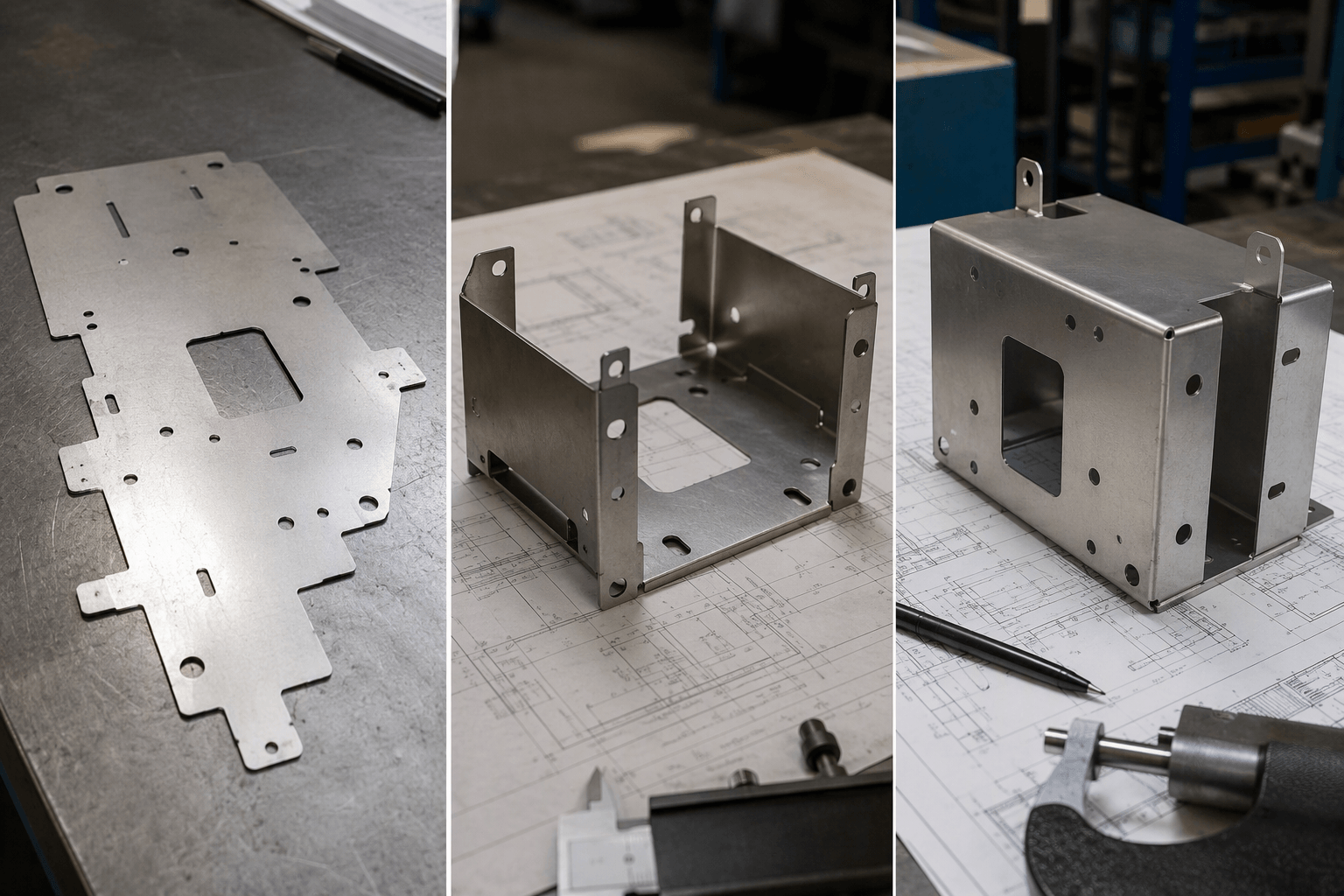
- Form the part. Press-brake bending or another forming operation changes the flat layout into the required geometry. Bend allowance, bend sequence, tooling, material behavior, and springback all influence the final position of features. A hole close to a bend, for example, deserves review because its location and shape can be affected by forming conditions.
- Join components when required. Welding, riveting, and adhesives are separate joining choices. Load, access, appearance, heat effects, service conditions, and the ability to inspect the joint should guide the selection. Welding may be appropriate for an assembly, but it is not what defines sheet metal fabrication.
- Apply and control the finish. Finishing may address corrosion protection, appearance, surface preparation, or functional requirements. The specification should identify the required finish, relevant surfaces, masking or coverage expectations, and any effect on fit or assembly.
- Inspect and document the result. Inspection can include dimensional measurement, visual checks, fit checks, and documented results against the drawing or agreed acceptance criteria. For a new or changing project, a first article or sample review may be useful before repeat production, but the exact approval workflow should be agreed by the buyer and fabricator.
Choosing Cutting, Forming, and Joining Methods
Process selection should follow the part rather than a supplier’s equipment list. The most suitable route depends on geometry, material, thickness, edge requirements, tolerances, quantity, tooling implications, and the next operation.
| Requirement | Possible process direction | Questions to resolve |
|---|---|---|
| Profile and hole features in sheet | Laser cutting may suit detailed profiles and controlled heat-affected edges; waterjet may be considered where a cold cutting process is useful; plasma may suit appropriate material and geometry requirements. | What edge condition, heat effect, hole quality, and secondary deburring are acceptable? |
| Angled flanges and formed channels | Press-brake bending provides a flexible route for formed features and requires attention to tooling, bend sequence, allowance, and springback. | Which dimensions are functional, and how will the bend sequence affect holes, datums, and assembly? |
| Repeated formed geometry at a suitable quantity | Stamping may offer a production-oriented approach when tooling investment and repeatability justify it. | Does the expected quantity support tooling, and who owns the tooling and controls design changes? |
| Multi-part assembly | Riveting, welding, or adhesives may be selected according to load, access, appearance, heat sensitivity, and service conditions. | What joint performance, cosmetic condition, distortion control, and inspection evidence are required? |
Laser, waterjet, and plasma are not interchangeable labels for accuracy. Each has different effects on edge condition, heat input, setup, speed, and secondary work, and the appropriate choice varies by material and design. Similarly, bending and stamping serve different production situations. A buyer should ask the fabricator to explain the proposed route and its tradeoffs instead of specifying a process without understanding its effect on the finished part.
Material, Geometry, and Tolerances That Affect Manufacturability
Material selection affects more than price. Weight, strength, corrosion resistance, forming behavior, surface appearance, and finishing requirements can all change the process decision. A material that meets the strength requirement may respond differently during bending or finishing than another material with similar nominal thickness. The drawing should therefore identify the required material clearly, and the supplier should explain any concern about availability, substitution, traceability, or forming behavior before production.
Geometry also determines risk. Bend radius, bend direction, flange relationships, hole size and location, edge distance, corner relief, and the order of operations can affect whether a part forms cleanly and remains stable through later operations. Critical holes may need to be cut, formed, or inspected in a sequence that protects their relationship to the final assembly datum. These decisions should be reviewed from the finished-part perspective, not only from the flat layout.
Tolerances should describe function rather than communicate an unnecessarily narrow target. Identify dimensions that control mating, movement, sealing, alignment, or structural fit. Separately identify cosmetic surfaces, general dimensions, hole requirements, squareness or flatness needs, and finish-related expectations. A fabricator can then assess whether the requested tolerance is appropriate for the selected material and process and can identify where a design change or additional control may be needed.
Inspection, Documentation, and Production Scaling
Inspection should be planned around the risks that matter to the application. Dimensional checks may focus on datums, bend angles, hole locations, overall size, and assembly interfaces. Visual checks may address scratches, edge condition, weld appearance, coating coverage, or other defined cosmetic requirements. Fit checks can confirm how the part works with a mating component. Documented results are more useful when the drawing identifies the characteristics being checked and the acceptance criteria are clear.
Prototype, low-volume, and larger production runs can require different controls. A prototype may be used to validate geometry, assembly, and finish before repeat production. Low-volume work may rely on controlled setups and review of each order. Larger runs place greater emphasis on repeatable tooling, process settings, revision control, inspection timing, and communication of changes. A sample made with a different process or material condition may not represent production performance, so the buyer should ask how the sample relates to the planned production route.
Change management is part of precision control. A material substitution, tooling change, revised bend sequence, altered finish, or supplier-side process change can affect fit and appearance even when the nominal drawing is unchanged. Before ordering, clarify how such changes will be communicated, whether approval is required, and which records will accompany the shipment.
Match the Part Requirement to the Fabrication Decision
| Part information to provide | Fabrication decision to discuss | Evidence or clarification to request |
|---|---|---|
| Material grade, thickness, and corrosion requirements | Material sourcing, forming route, edge treatment, and finish | Material identification, substitution rules, and traceability expectations |
| Critical dimensions, datums, holes, and mating features | Cutting sequence, bend sequence, tooling, and inspection points | Technical review comments and a clear acceptance plan |
| Quantity by prototype, low-volume, or production stage | Setup control, tooling investment, process repeatability, and sample approval | Tooling ownership, production transition, and revision-control method |
| Cosmetic surfaces and functional finish | Deburring, joining, surface preparation, finishing, and packaging | Finish coverage, protected surfaces, visual criteria, and packaging approach |
| Assembly and downstream requirements | Joint selection, fit checks, orientation control, and inspection documentation | How nonconformities, changes, and inspection records will be handled |
What to Verify Before Choosing a Fabricator
A supplier review should test technical understanding rather than rely on generic claims. Ask how the fabricator interprets the drawing, which features it considers critical, and what assumptions must be resolved before quoting. Confirm the proposed material source, traceability approach, tolerance review, tooling ownership, sample or first-article approval, inspection records, finishing controls, packaging, and production-change communication.
Ask for evidence that relates to the project: a marked-up drawing review, a process explanation, a sample inspection record when applicable, or a description of how the supplier will control a repeated feature. The objective is not to demand an identical process for every part. It is to establish that the supplier can connect requirements to process controls and communicate limits or risks before they become production problems.
For enclosure projects, review not only the cut and bend features but also the assembly interfaces, finish, and protection of visible surfaces. For brackets, focus on mating holes, bend position, load-related features, and the datum used for inspection. For frames, clarify squareness, stability, joint condition, and assembly fit. These project types can be discussed through relevant examples such as custom sheet metal enclosures, custom metal brackets, and custom metal frames, while the actual acceptance criteria should remain specific to the buyer’s drawing.
OEM and ODM buyers that need design collaboration should also separate design assistance from manufacturing approval. A fabricator may help identify bend, hole, material, or assembly concerns, but the buyer should approve any change to function, appearance, material, or acceptance criteria.
Where RFQ Assumptions Create Cost and Production Risk
Many sheet metal fabrication problems begin before production starts. If drawings, tolerances, finish expectations, material grades, or assembly requirements are unclear, suppliers may quote based on different assumptions. That can make prices difficult to compare and may lead to rework, cosmetic rejection, assembly misalignment, or production delays later.
For OEM buyers, the goal is not simply to request the lowest price. The goal is to make sure each supplier is quoting the same manufacturing reality. Before confirming an order, clarify which dimensions are fit-critical, which surfaces are cosmetic, whether prototypes must match batch-production conditions, and how finished parts will be inspected.
Frequently Asked Questions
What laser cutting precision details should buyers define before requesting a quote?
Buyers should define the functional requirement, drawing notes, critical dimensions, material or process expectations, and any inspection points related to laser cutting precision. This helps suppliers quote the same manufacturing scope instead of making different assumptions.
How can cut hole locations affect cost, fit, or lead time?
cut hole locations can change tooling, forming, welding, finishing, inspection, or rework requirements. If buyers do not clarify it early, two supplier quotes may look comparable while covering different production risks.
Why should bend-to-hole dimensions be reviewed before prototype approval?
bend-to-hole dimensions may look acceptable on a single sample but become harder to control during batch production. Buyers should confirm whether the prototype reflects the same process, finish, and inspection conditions expected for production.
What inspection points matter most for precision sheet metal fabricators projects?
Important inspection points usually include fit-critical dimensions, holes or mating areas, cosmetic surfaces, finish build-up, welded or formed features, and any dimensions that affect downstream assembly. These points should appear in the RFQ or drawing notes.
How can buyers reduce batch consistency risk before batch production?
Buyers can reduce risk by clarifying drawings, locking key material and finish assumptions, defining inspection timing, approving a representative sample, and confirming which dimensions or surfaces require tighter process control.
How can Yishang help review precision sheet metal fabricators requirements?
Yishang can review drawings, RFQ notes, material requirements, tolerance expectations, finish details, samples, and assembly needs to identify unclear assumptions before quoting or batch production.