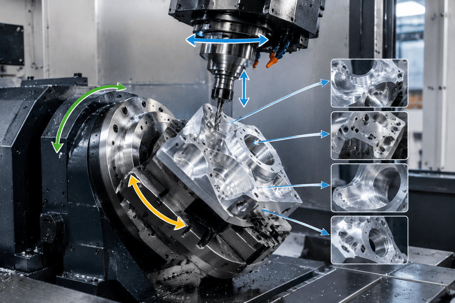
A 6 axis CNC machine coordinates six directions of tool and workpiece movement to reach complex features from multiple orientations. The additional motion can help with angled surfaces, compound contours, multi-sided access, and features that are difficult to machine after repeated repositioning. It does not automatically make every part more accurate, faster, or less expensive. The right choice depends on the part geometry, material, dimensions, tolerances, surface finish, quantity, workholding, programming requirements, and inspection plan.
For early process selection, the practical question is not simply whether a machine has six axes. It is whether coordinated six-axis movement solves an access or setup problem that a simpler or different process cannot address efficiently. A technical feasibility review should establish that relationship before a supplier quotes the work.
What Does a 6 Axis CNC Machine Mean?
A CNC machine uses programmed movement to control a cutting tool, a workpiece, or both. The movement usually combines linear travel along three directions with rotary movement around one or more axes. A six-axis machine therefore has six coordinated motion directions, although the physical arrangement varies by machine configuration. Some machines move the tool through several orientations, some rotate or tilt the workpiece, and others combine both approaches.
Axis naming and the location of each rotary axis are not universal. The sixth axis may be arranged differently depending on the machine architecture, spindle system, table, fixtures, and control strategy. For that reason, an axis count alone does not describe the available working envelope or prove that a particular part can be machined in one setup.
The useful change is coordinated access. The control system can synchronize linear and rotary movement so the tool approaches a surface at a suitable orientation while the workpiece remains correctly located. This can support machining on multiple faces, angled holes, compound surfaces, and contours that would otherwise require additional setups or specialized workholding.
That capability also creates requirements. The tool must have a clear path, the fixture must hold the part without blocking the cut, and the programmed motion must maintain the intended relationship between the tool, part, and datum system. Inspection must then confirm the features from the same functional references used during design and manufacture.
Where Six-Axis Motion Adds Practical Value
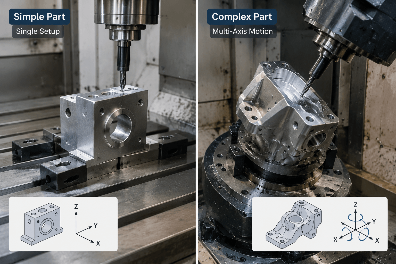
Six-axis machining can be appropriate when geometry and access are closely connected. A part may have a simple overall shape but still contain features that are difficult to reach because a wall, boss, flange, or deep pocket blocks a straight tool approach. Coordinated rotary movement can provide another approach direction and reduce the need to remove and reposition the part.
Potentially suitable characteristics include:
- Multiple functional surfaces that must be related to one another.
- Angled holes, faces, or ports that do not align with the primary machine directions.
- Compound contours requiring changing tool orientation across the surface.
- Deep or obstructed features where a direct approach creates tool, holder, or fixture interference.
- Parts with several machining sides where repeated setups could complicate datum control.
- Geometries where maintaining access through a continuous tool path is more useful than machining each face separately.
Reduced repositioning may improve consistency because the part can remain located while more features are reached. That is a possible process benefit, not a universal result. A complex fixture, difficult verification, or extensive programming may offset the value of fewer setups. In some cases, a three-axis or five-axis process with a practical fixture remains the better choice. In other cases, turning, sheet metal fabrication, welding, or a combined route addresses the actual manufacturing need more directly.
Consider a machined housing with a primary mounting face, intersecting angled passages, and a recessed feature behind a raised wall. The key question is not whether the housing looks complex. The question is whether the required tool paths can reach those passages and preserve their relationship to the mounting datum without excessive repositioning. A six-axis review would examine tool clearance, fixture access, datum strategy, and inspection access before recommending the process.
A second example is a formed enclosure that includes a few machined holes and mounting pads. The enclosure may need sheet metal cutting, bending, joining, finishing, and assembly, while the machined features are only one part of the route. Six-axis machining would not replace the forming and joining operations. The appropriate solution could be a combined manufacturing process, with the machining method selected only for the features that require it.
6 Axis Machining Compared With Related Processes
Machining removes material from a workpiece, commonly from a solid billet, casting, forging, or other prepared form. Related processes address different starting conditions or manufacturing actions. Understanding the boundary prevents a complex part from being assigned to six-axis machining simply because it has several features.
| Process | What it primarily does | When it may be the relevant route |
|---|---|---|
| 6 axis CNC machining | Removes material while coordinating multiple linear and rotary movements. | Complex access, compound angles, multi-sided features, or obstructed geometry justify coordinated motion. |
| 5 axis or 3 axis machining | Uses a different level of coordinated motion and machine configuration. | The part can be reached and held effectively with a simpler setup or axis arrangement. |
| CNC turning | Rotates the workpiece while a tool removes material from rotationally related geometry. | The main features are cylindrical, concentric, or otherwise suited to a turning process. |
| Sheet metal fabrication | Cuts, forms, bends, and may join sheet or plate components. | The design is based on formed panels, bends, flanges, and relatively thin material rather than a machined solid. |
| Welding | Joins separate components into a larger assembly. | The required structure is made by joining parts rather than removing material from one workpiece. |
| Finishing | Changes surface condition, appearance, corrosion resistance, or other specified surface properties. | The operation follows cutting or forming and does not create the primary part geometry. |
| Assembly | Combines manufactured components into a functional unit. | The project requires installation, fastening, alignment, or integration of multiple parts. |
Hybrid projects are common. A machined bracket may later receive finishing and assembly. A sheet metal enclosure may include machined inserts or accurately prepared mounting features. A turned component may require milling on selected faces. The manufacturing route should follow the drawing, material condition, functional surfaces, and required inspection points rather than the most advanced machine available.
For related context, custom metal brackets built to your drawings should be evaluated from their actual geometry and production requirements. Likewise, custom sheet metal enclosures that arrive ready to assemble may combine formed, machined, finished, and assembled features without making six-axis machining the primary process.
Requirements That Determine Feasibility
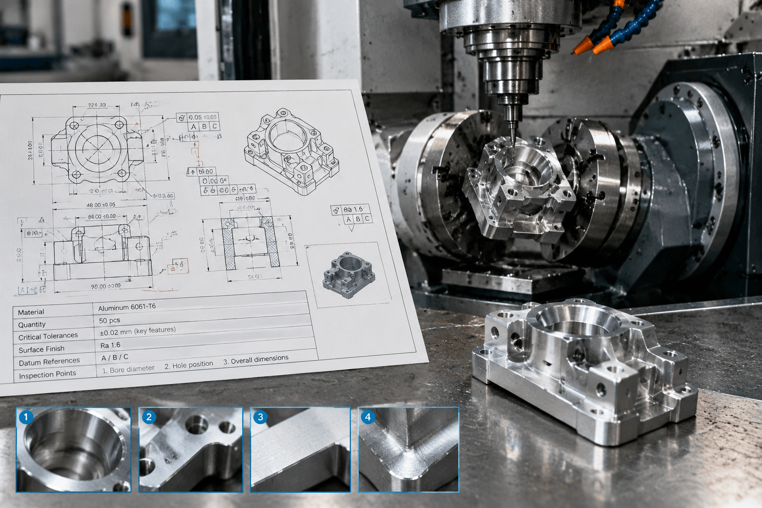
A useful feasibility review starts with complete product information. Provide a current 3D CAD file or technical drawing, material and material condition, overall dimensions, critical tolerances, surface finish requirements, expected quantity, revision status, and inspection expectations. These details let the manufacturing team assess not only whether the tool can reach the part, but also whether the proposed route can control the features that matter functionally.
Separate critical requirements from general dimensions. A mounting interface, bearing seat, sealing surface, hole pattern, or datum-related feature may need closer attention than a non-functional outside surface. The drawing should identify the relationships that affect fit and operation. Unnecessarily tight tolerances can increase process complexity, but relaxed requirements should be based on function rather than assumed from a standard process.
Material affects tool selection, cutting conditions, workholding, surface condition, and inspection considerations. Dimensions affect the available working envelope, fixture design, and tool reach. Surface finish may influence tool paths, finishing passes, or a separate finishing operation. Quantity affects whether the setup and programming effort is appropriate for the project, but quantity alone does not determine whether six-axis machining is suitable.
Workholding and datum strategy deserve early review. A fixture must hold the part securely while exposing the required surfaces and avoiding interference with the tool, holder, spindle, or rotary movement. The chosen datums should support both machining and inspection. If a part must be removed and reoriented, the process needs a repeatable method to preserve feature relationships across setups.
Inspection requirements should be defined before production rather than treated as an afterthought. Identify the dimensions, angles, positions, surfaces, and assembly interfaces that require verification. The inspection method must suit the geometry and the specified tolerance. A technically accessible feature may still require a different inspection approach if its location, orientation, or relationship to another feature is critical.
Yishang can review a 3D CAD file or drawing together with material, dimensions, tolerances, surface finish, quantity, inspection requirements, and any critical access, datum, or assembly constraints. That review can help clarify whether machining, sheet metal fabrication, or a combined process is the more appropriate route for an OEM or ODM project.
Keeping the Process Consistent From Prototype to Batch
Prototype approval should confirm more than the appearance of one sample. It should confirm that the part functions as intended and that the selected manufacturing method can be repeated under the planned production conditions. This is particularly important when the part depends on multiple datums, angled features, or a fixture that controls several accessible faces.
Useful controls include setup documentation, defined datum references, approved workholding details, revision control, inspection records, and clear identification of critical features. The production record should make it possible to understand which drawing revision, fixture arrangement, program revision, and inspection requirements apply to a part. These controls support continuity when a project moves from prototype quantities to repeat production.
The prototype process does not need to be identical in every detail to the eventual batch route, but the differences should be understood. A prototype made with temporary workholding may not demonstrate the same repeatability as a planned production fixture. Conversely, a production-oriented setup may be unnecessary for a one-off evaluation. The important point is to confirm which risks are being tested and which remain open.
Does Your Part Need 6 Axis CNC Machining?
| Review question | What a positive answer may indicate | What still needs confirmation |
|---|---|---|
| Does the part have several surfaces, compound angles, or obstructed features? | Additional coordinated motion may improve tool access. | Tool clearance, holder interference, and fixture access. |
| Would repeated repositioning threaten datum or feature relationships? | A process with more coordinated access may reduce setup changes. | Whether the machine and fixture can actually hold the part repeatably. |
| Are the critical tolerances or finishes concentrated on accessible machined features? | Machining may be appropriate for those functional areas. | Tool path strategy, material behavior, and inspection method. |
| Is the part primarily formed sheet, rotational stock, or a welded assembly? | A different primary process may be more suitable. | Whether machining is needed for inserts, interfaces, or secondary features. |
| Are quantity and revision requirements clearly defined? | The setup and documentation effort can be evaluated realistically. | Prototype-to-batch consistency and control of future revisions. |
A six-axis recommendation should follow this review, not replace it. Ask the supplier to explain how the proposed configuration reaches the critical features, how the part will be held, which datums control each operation, and how the specified requirements will be inspected. This creates a technical basis for comparing processes without assuming that a higher axis count is automatically better.
Frequently Asked Questions
What 6 axis cnc machine details should buyers define before requesting a quote?
Buyers should define the functional requirement, drawing notes, critical dimensions, material or process expectations, and any inspection points related to 6 axis cnc machine. This helps suppliers quote the same manufacturing scope instead of making different assumptions.
How can RFQ details affect cost, fit, or lead time?
RFQ details can change tooling, forming, welding, finishing, inspection, or rework requirements. If buyers do not clarify it early, two supplier quotes may look comparable while covering different production risks.
Why should drawing requirements be reviewed before prototype approval?
drawing requirements may look acceptable on a single sample but become harder to control during batch production. Buyers should confirm whether the prototype reflects the same process, finish, and inspection conditions expected for production.
What inspection points matter most for 6 axis cnc machine projects?
Important inspection points usually include fit-critical dimensions, holes or mating areas, cosmetic surfaces, finish build-up, welded or formed features, and any dimensions that affect downstream assembly. These points should appear in the RFQ or drawing notes.
How can buyers reduce prototype approval risk before batch production?
Buyers can reduce risk by clarifying drawings, locking key material and finish assumptions, defining inspection timing, approving a representative sample, and confirming which dimensions or surfaces require tighter process control.
How can Yishang help review 6 axis cnc machine requirements?
Yishang can review drawings, RFQ notes, material requirements, tolerance expectations, finish details, samples, and assembly needs to identify unclear assumptions before quoting or batch production.