
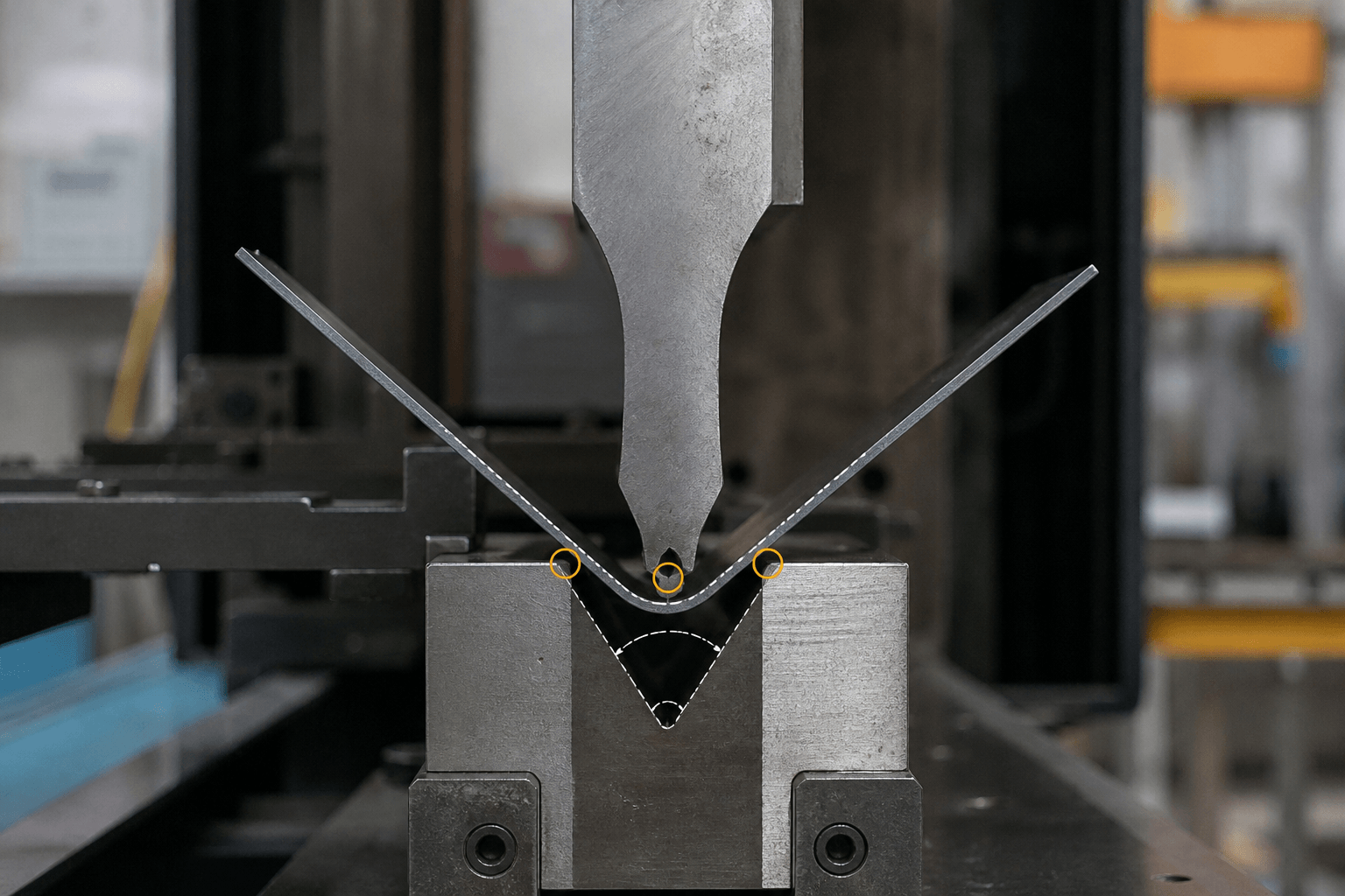
Air bending sheet metal is a press-brake forming method in which the workpiece contacts the punch tip and the two shoulders of a V-die without fully conforming to the die cavity. The bend angle is produced mainly by controlling punch penetration, while the resulting inside radius and springback depend on the material, thickness, grain direction, tooling geometry, and setup.
These relationships matter before production begins. A drawing may define the required formed dimensions, but the flat pattern, bend locations, reliefs, and inspection method must also reflect how the material will behave during and after forming.
How the Three-Point Bending Process Works
During air bending, a punch presses the sheet into an open die. The sheet is supported at the two die shoulders and loaded at the punch tip, creating three principal contact points. Unlike bottoming or coining, the sheet is not seated against the die angle or driven into full tool conformity; contact remains concentrated at the punch tip and die shoulders.
As the punch moves farther into the die opening, the included angle becomes smaller. Retracting the punch releases the load, after which the material elastically recovers by some amount. This recovery is springback, and it means the angle under load is not necessarily the final angle after unloading.
The incomplete contact between the sheet and die gives air bending considerable flexibility. One punch-and-die combination may form more than one angle by changing penetration. That flexibility, however, makes the outcome sensitive to material variation, tooling condition, positioning, and the accuracy of the press-brake setup.
What Controls the Bend Angle and Inside Radius?
The finished bend is the result of interacting variables rather than one universal tooling rule. Designers should treat the following factors as connected inputs.
Punch travel and die opening
Deeper punch penetration generally produces a more acute included angle. The programmed travel must account for elastic recovery, so the sheet is commonly formed beyond the target angle and allowed to spring back toward the required condition.
The V-die opening influences how the sheet wraps around the punch and where plastic deformation develops. A wider opening will generally produce a larger naturally formed inside radius and require a longer supporting flange, while a narrower opening changes the radius, forming load, and risk of marking or cracking. The appropriate opening depends on thickness, alloy, temper, geometry, tooling, and equipment limits.
Punch geometry and the naturally formed radius
In air bending, the inside radius is not always an exact reproduction of the punch-tip radius. It often develops naturally from the die opening and the material’s response to strain. The punch tip still matters because it affects contact pressure and whether the sheet is being formed normally or forced around a radius that is too sharp for the material.
Consequently, a drawing should not assume that any specified radius can be created with any punch and die. A small requested radius may require a different method, tooling review, or design adjustment, particularly in less ductile materials.
Material, thickness, and grain direction
Yield strength, tensile strength, elastic modulus, ductility, temper, surface condition, and thickness variation all influence bending behavior. Higher-strength or harder material often exhibits greater springback and may need a larger bend radius to reduce cracking risk. These tendencies vary by grade and condition.
Rolling direction also affects formability. Bending across the grain is generally less prone to cracking than bending with the bend line parallel to the grain, although the actual requirement depends on the alloy, temper, radius-to-thickness relationship, and applicable material specification. Grain direction should therefore be identified when it is functionally important.
Nominal geometry versus production geometry
The drawing defines the desired finished part, not the exact punch depth or compensation needed to make it. The manufacturer must translate nominal angles, radii, and flange dimensions into a workable tool setup and flat pattern. Critical dimensions should be tied to clear datums, and inspection should occur in the same restrained or unrestrained condition intended by the drawing.
Designing a Flat Pattern That Can Be Formed
Air-bent parts should be designed from the relationship between the finished geometry and the developed blank. Copying outside flange dimensions directly into a flat layout will usually produce dimensional error because material is consumed through the bend zone.
Bend allowance, bend deduction, and K-factor
Bend allowance is the developed arc length through the bend zone, measured along an assumed neutral axis. A common calculation form is BA = angle in radians × (inside radius + K × thickness). The angle definition must match the drawing and calculation convention.
K-factor expresses the neutral-axis position as a fraction of material thickness. It is not a universal material constant. It can change with the material, thickness, bend radius, die opening, forming method, and degree of deformation. Proven bend data or manufacturing feedback is preferable to applying one default value to every design.
Bend deduction is the amount subtracted from the sum of the outside flange dimensions to obtain the flat length. For a simple bend, it is derived from the outside setbacks and bend allowance. CAD software may calculate these values automatically, but its bend table, K-factor, or deduction settings still need to match the intended production process.
Flange length and tool support
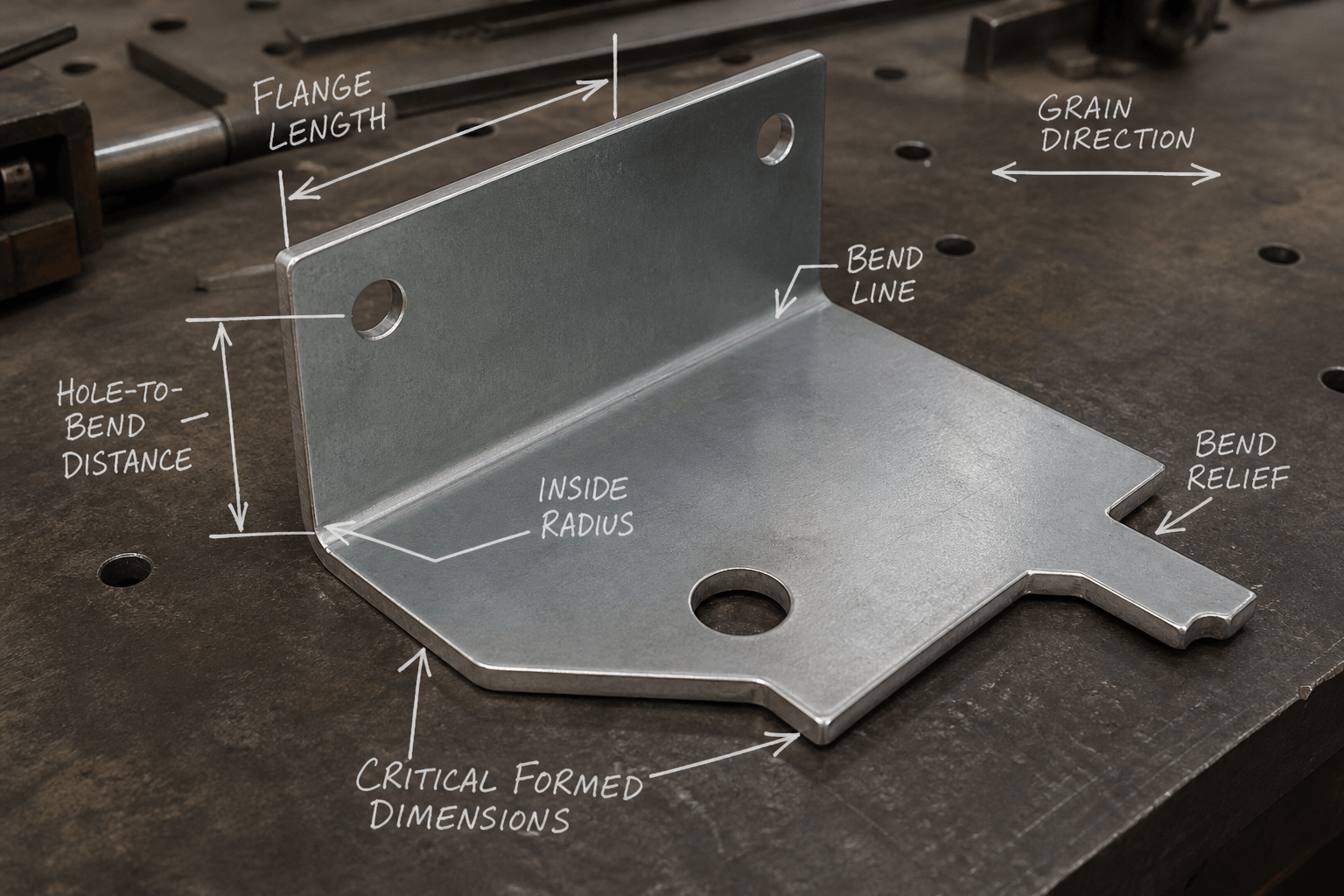
A flange must remain supported on the die shoulders during forming. If it is too short for the selected opening and geometry, the edge may drop into the die, slide unpredictably, or prevent stable positioning. Minimum flange length is therefore a tooling-access question, not just a drawing preference.
This is especially relevant to custom metal brackets built to drawing, where short return flanges, closely spaced holes, and multiple bends can compete for limited space.
Holes, slots, and edges near the bend
Material within or close to the bend zone stretches and compresses. Holes and slots placed too near that zone may become oval, shift position, or pull toward the bend. Edges may also flare or distort. The required separation should be reviewed using the material thickness, inside radius, feature size, and intended tooling rather than a universal spacing rule.
If a functional feature must be close to a bend, possible responses include changing its position, modifying the blank, forming before creating the feature, or accepting controlled deformation where function permits. The suitable option depends on the part and production route.
Reliefs, corners, and bend sequence
Bend reliefs can reduce tearing, overlap, and corner bulging where a bend ends near an edge or intersects another flange. Relief width, depth, and shape should be sufficient for the deformation zone without unnecessarily weakening the corner.
Multi-bend parts also need a feasible forming sequence. A flange that is easy to form in isolation may collide with the punch, die, backgauge, or press-brake structure after an earlier bend. This is common in custom sheet metal enclosures, where returns, corner seams, and opposing flanges restrict later tool access. Reviewing the sequence before release can prevent a finished design from requiring special tooling or geometric changes.
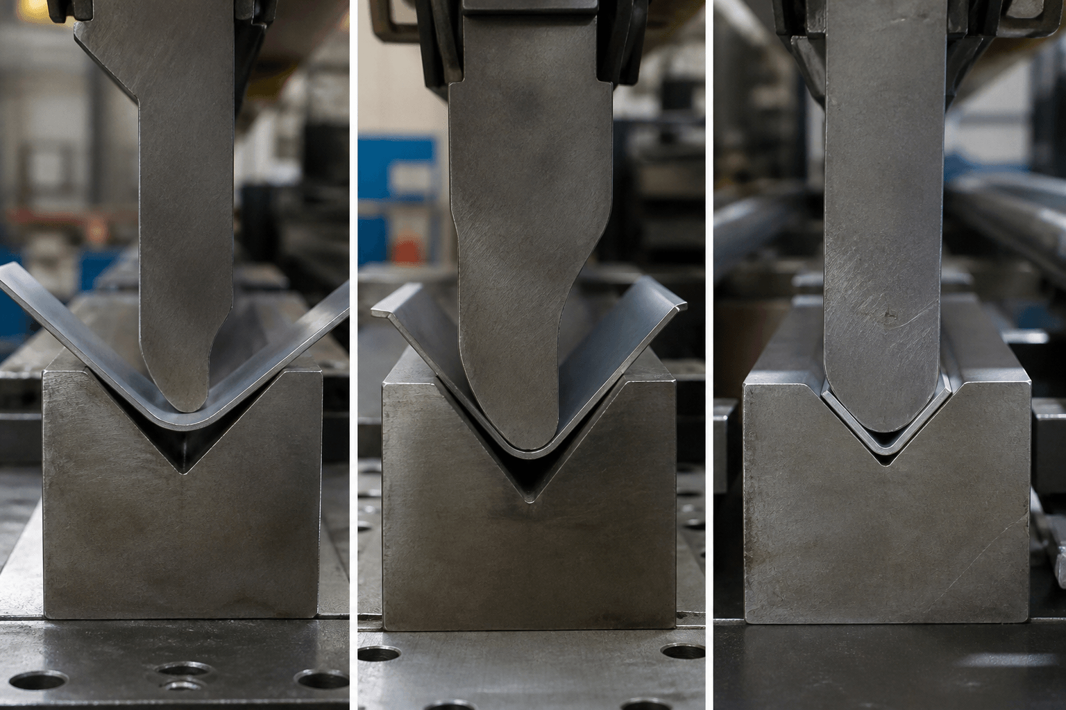
Air Bending, Bottoming, and Coining Compared
All three methods use press-brake tooling, but they differ in sheet-to-tool contact and how the final angle is established. None is automatically best for every part.
| Factor | Air bending | Bottoming | Coining |
|---|---|---|---|
| Tool contact | Three principal contact points; sheet does not fully seat in the die | Sheet is pressed into closer contact with the punch and die surfaces | High localized pressure forces material to conform closely to the tooling |
| Angle control | Primarily controlled by punch penetration and compensation | Strongly influenced by the tooling angle and final seating condition | Established through substantial material compression and tool conformity |
| Tooling flexibility | One setup may produce multiple angles within practical limits | Tool angle is more closely tied to the desired bend | Requires tooling and conditions suited to the target geometry |
| Springback sensitivity | Requires active consideration because elastic recovery remains significant | Reduced relative to air bending in suitable conditions, but not eliminated | Material compression can greatly reduce springback |
| Force demand | Generally lower than methods involving full seating or heavy compression | Generally higher than air bending | Typically the highest of the three |
| Selection basis | Useful when angle flexibility and adaptable tooling are important | Considered when closer tool conformity suits the material and geometry | Reserved for applications where its forming characteristics justify the force and tooling requirements |
Method selection should consider the required geometry, material behavior, surface expectations, available tooling, production volume, and dimensional requirements. Air bending should not be specified solely on an assumption that it is more accurate than bottoming or coining.
Diagnosing Common Air-Bending Problems
When a formed part does not match the drawing, the cause may originate in the design, flat pattern, material, tooling, or machine setup. Separating these categories helps avoid correcting one bend while creating another problem.
| Observed problem | Likely causes | Review direction |
|---|---|---|
| Angles vary between parts | Material strength or thickness variation, inconsistent grain orientation, changing springback, positioning error, or tooling condition | Verify the material condition and orientation, inspect tooling and gauging, and adjust compensation using representative production material |
| Inside radius differs from the drawing | Requested radius does not match the natural radius produced by the die opening, material, thickness, and punch geometry | Review the radius specification against the proposed tooling and determine whether the radius is functional or nominal |
| Cracking at the outside surface | Radius too small, low ductility, unfavorable grain direction, damaged edge, or excessive localized strain | Consider a larger radius, different orientation, improved edge condition, or a material condition suitable for forming |
| Incorrect flange dimension | Wrong bend deduction, inaccurate bend location, inconsistent gauging, or measuring from an unsuitable datum | Confirm the flat-pattern calculation, datum scheme, setup position, and formed-part inspection method |
| Hole or slot distortion | Feature lies within the deformation zone or lacks adequate material between the bend and edge | Move the feature, revise the bend geometry, change the operation order, or define acceptable distortion |
| Tearing or bulging at a corner | Missing or undersized relief, intersecting bend zones, or unsuitable corner treatment | Add or revise the relief and check how adjacent flanges move during forming |
| Later bend cannot be reached | Earlier bends create tool or machine interference | Change the bend sequence, modify flange geometry, or review alternative tooling before finalizing the blank |
For a technical drawing review before quotation or production planning, Yishang can assess whether the bend geometry, flat-pattern assumptions, feature locations, and proposed forming sequence appear suitable for a B2B OEM or ODM project. Send the part drawing or 3D model, material specification and thickness, critical bend angles, radii, dimensions, and tolerances, plus the expected order quantity or production context. This review can identify points that need clarification without requiring an immediate quotation request.
Information Needed to Review an Air-Bent Part
A technically useful design review should identify the following inputs rather than relying on a simplified model alone:
- Material: alloy or grade, temper or condition where relevant, thickness, and any substitution restrictions.
- Finished geometry: required bend angles, inside radii, flange lengths, bend locations, and overall formed dimensions.
- Critical requirements: dimensional tolerances, angular tolerances, inspection datums, mating features, and whether dimensions apply in a free or restrained state.
- Grain direction: mandatory orientation, preferred orientation, or permission to optimize nesting and formability.
- Flat-pattern status: whether the supplied blank is mandatory or may be adjusted to suit validated bend deductions.
- Nearby features: hole, slot, cutout, embossment, edge, relief, and corner locations that could enter a bend zone.
- Production context: expected order quantity, repeat-production needs, and whether prototype feedback may be used to refine the developed blank.
Providing both flat and formed views can be helpful, but they must not conflict. When the finished dimensions are functionally controlling, the drawing should state that priority and allow the flat pattern to be developed for the agreed bending process.
Frequently Asked Questions
Does air bending require the sheet to touch the bottom of the die?
No. In normal air bending, the sheet contacts the punch tip and the two die shoulders but does not fully contact the bottom or angled faces of the die cavity. The bend is controlled by punch penetration rather than complete seating.
What determines the inside bend radius in air bending?
The radius develops from the interaction of die opening, sheet thickness, material properties, punch geometry, and penetration. It is often a naturally formed radius rather than an exact copy of the punch tip, so the requested radius should be reviewed with the proposed tooling.
Why does springback vary between materials or production batches?
Springback changes with yield strength, elastic modulus, temper, thickness, rolling direction, and the relationship between bend radius and thickness. Normal variation within a material specification can therefore change the released angle, requiring setup compensation based on representative material.
How are bend allowance and bend deduction used to create the flat pattern?
Bend allowance represents the developed length through the bend zone along the assumed neutral axis. Bend deduction converts outside formed dimensions into a flat length by accounting for the setbacks and bend allowance. Both depend on the selected geometry and process assumptions.