
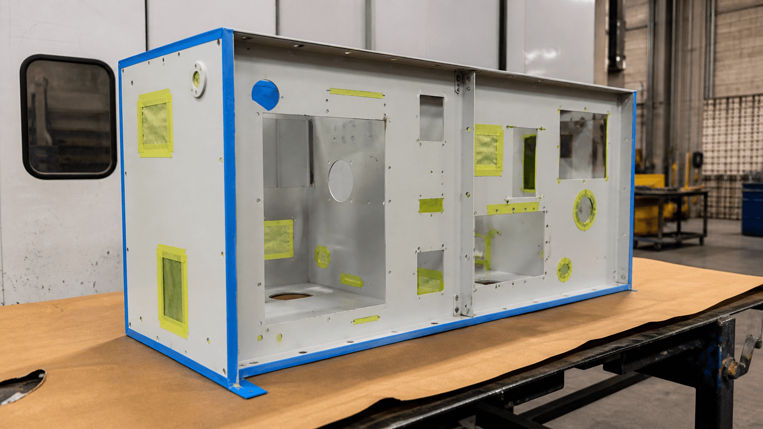
Metal powder coated means a fabricated metal part is covered with a dry powder coating that is electrostatically applied, then melted and cured into a continuous film. It describes a surface finish, not powder metallurgy, which forms a component from metal powder.
When an overseas OEM writes metal powder coated on an aviation metal fabrication drawing, the phrase does not tell the fabricator enough to quote or inspect the part consistently. A cabinet or bracket may meet its cut and bend dimensions yet still need decisions about pretreatment, masking, coating access, functional surfaces, and appearance approval.
In aviation metal fabrication, powder coating normally follows sheet-metal cutting, punching, metal bending, deburring, and required welding. It is a finishing step, not a substitute for those operations, CNC machining, or assembly; the final result depends on the substrate, surface condition, geometry, coating system, and agreed inspection criteria.
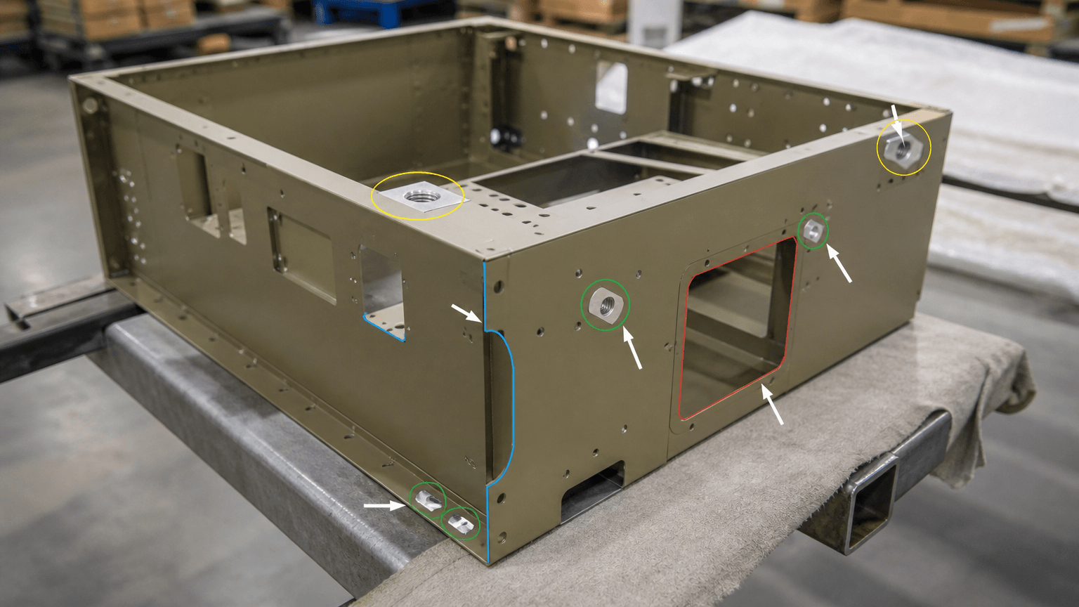
If a sheet-metal assembly includes a component produced by CNC turning or CNC milling, such as an insert, spacer, shaft, or mounting block, that component remains separately machined. Specify its material, dimensions, surface treatment, installation sequence, and interfaces separately from the sheet-metal and powder-coating notes.
How fabricated parts become powder coated
For a buyer reviewing an RFQ, the coating route begins before the part reaches the spray booth. Fabrication sequence, access, and assembly interfaces can determine whether the requested finish is practical and repeatable.
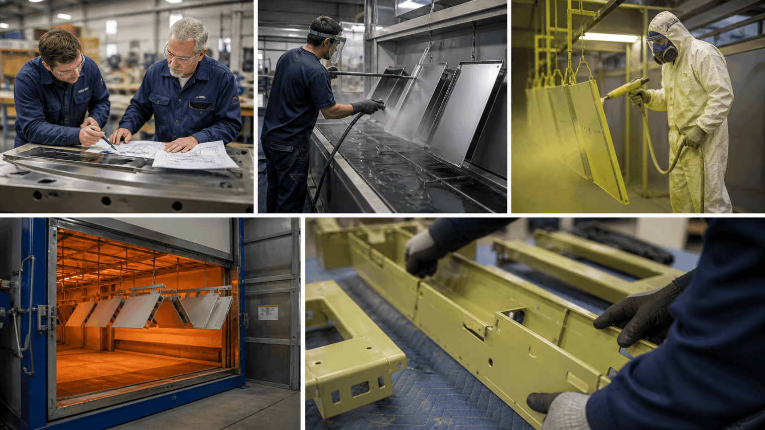
- Complete and review fabrication. Finish laser cutting, CNC punching, metal bending, welding, deburring, and separately specified machining. Before finishing, verify dimensions, weld condition, coating access, and assembly interfaces; decide whether final assembly or machined components come before or after coating.
- Clean and prepare the substrate. Remove oil, dirt, rust, oxide, welding residue, and other contamination as applicable. Degreasing, washing, derusting, phosphating, or abrasive preparation may be appropriate, but the route must match the substrate and coating system.
- Rack and mask the part. Hang it to expose the required faces and provide suitable electrical contact for electrostatic application. Mask threads, holes, grounding pads, labels, mating faces, and other controlled areas identified on the drawing. Choose rack locations so contact marks remain in an acceptable area.
- Apply the powder. Charged powder particles are sprayed toward the grounded metal surface and attracted to it. Gun access, orientation, corners, recesses, and the electrical path influence coverage.
- Heat-cure the film. The part enters a heated curing stage where the powder melts and cures. Required heat exposure depends on the powder system, substrate, part mass, loading pattern, and project specification; a generic supplier setting should not replace the agreed requirement.
- Inspect before release. Check preparation and cleanliness as required, then review coverage, appearance, masking, rack-contact areas, curing evidence where specified, critical dimensions, and assembly fit.
Because finishing follows fabrication, reviewing Custom Sheet Metal Fabrication Built to Your Drawings can help teams separate cutting, forming, welding, and coating decisions instead of treating them as one operation.
Substrate and geometry decide coating suitability
During an early project review, a material callout alone is not enough to predict finish quality. A mild-steel cabinet, an aluminum bracket, and a welded galvanized frame may all be specified as powder coated, but their surface conditions, preparation needs, and access points differ.
Material condition and preparation
Mild steel can carry oil, mill scale, or rust. Aluminum fabrication involves an oxide surface; galvanized steel has a zinc surface; and stainless steel fabrication requires controlled cleanliness and a preparation method compatible with the surface and coating system. No single pretreatment route should be assumed across these materials.
Weld spatter, heat scale, grinding dust, fingerprints, oil, and cleaning residue can affect adhesion or visible appearance. Welded cabinets and frames can also have crevices that retain fluid or limit powder access, so weld cleanup should be reviewed from the actual joint condition.
Geometry, access, and production planning
Sharp edges, narrow returns, deep corners, and recessed pockets can change particle access and film distribution. Electrostatic shadowing may reduce coverage in some areas, while powder buildup can reduce clearance in holes and threads. Mark these locations as coated, controlled-coat, or no-coat areas when they carry an electrical, fastening, sealing, or fit function.
Dimensions, weight, hanging orientation, rack contact, and oven or loading constraints determine whether all required faces can be coated without fixture interference. A large welded enclosure may therefore need a different hanging plan from a small bracket, even with the same finish reference.
Masking complexity, color changeover, batch size, rework, handling, and inspection scope add process steps that affect cost and lead time. Review these factors early for Custom Sheet Metal Enclosures That Arrive Ready to Assemble, where access, mating faces, grounding points, rack marks, and fit may all matter.
From metal powder coated to an executable requirement
For a buyer, writing only metal powder coated on a drawing leaves important decisions open to interpretation. The table below turns that shorthand into inputs that engineering, procurement, fabrication, finishing, and inspection teams can use consistently.
| Drawing or RFQ field | What to define |
|---|---|
| Part and process boundary | Identify the part number and coated surfaces. State whether it is a sheet-metal detail, welded assembly, or assembly containing separately machined components. |
| Substrate and thickness | State the base metal type or grade, surface condition where relevant, and material thickness. |
| Coating identity | Provide the powder or approved coating reference, color code, revision, and an approved physical or digital sample when needed. |
| Appearance | Define gloss, texture, visible-surface expectations, viewing condition, and acceptable variation or defect criteria. |
| Pretreatment | State the required cleaning or pretreatment route, weld preparation, and whether an alternative requires approval. |
| Film and cure | State the target film thickness, measurement locations and method, cure requirements, and evidence to record. Do not insert values unless the project defines them. |
| Functional areas and sequence | Mark threads, holes, grounding pads, labels, mating, bearing, sealing, and weld interfaces as coat, controlled-coat, or no-coat. State whether machined components are installed before coating or fitted afterward. |
| Edges and racking | Define edge-coverage expectations, preferred hanging points, permitted rack marks, and areas where contact marks are unacceptable. |
| Acceptance and inspection | Define color, gloss, texture, coverage, surface defects, critical dimensions, assembly fit, and any film-thickness, adhesion, cure, or corrosion test using an agreed method. |
| Quantity and handling | Include prototype and production quantities, batch grouping, packaging, labeling, inspection records, and target delivery timing. |
A physical or digital finish sample is useful when appearance approval and batch consistency matter. The Surface Finishing overview can support a discussion of which route fits the substrate, appearance, and functional interfaces.
Finish selection depends on the part
During finish selection at the RFQ stage, compare powder coating with alternatives against the part’s function rather than a generic preference. Substrate, environmental exposure, appearance, electrical contact, dimensional fit, part size, batch volume, and required performance all influence the decision.
| Route | Process and selection considerations |
|---|---|
| Powder coating | Dry powder is electrostatically applied and heat-cured into a polymer film. Review heat compatibility, access, masking, film buildup, appearance, and the defined coating system. |
| Liquid spray paint | A wet coating is sprayed and then dried or cured. Consider application and drying conditions, overspray control, repair approach, and thickness-control requirements. |
| Electroplating | An electrochemical process deposits a metal layer rather than a cured polymer powder film. Review electrical contact, dimensional buildup, base material, and the required metal surface. |
| Anodizing | An electrochemical surface-conversion process primarily associated with aluminum. Evaluate substrate compatibility, appearance, masking, and dimensional interfaces. |
| Galvanizing | A zinc-based coating route with different geometry, dimensional, and downstream-finishing considerations. Review design requirements, venting or drainage where applicable, and fit. |
These processes are not interchangeable labels. A finish suitable for a visible enclosure panel may be unsuitable for a grounding pad, close-fit joint, threaded hole, or chemically demanding environment. The coating system and inspection method should follow the part’s actual function and exposure.
Approval and troubleshooting at the production handoff
At first-article or sample approval, the buyer should connect finish appearance with fabrication and assembly function. Compare color, gloss, texture, visible defects, masking, rack marks, critical dimensions, and fit against the approved reference under an agreed viewing and inspection condition.
For each batch, inspect specified visible and hidden faces, coverage, holes and threads, grounding areas, mating surfaces, and assembly fit. Compare production parts with the approved reference under the same conditions, and use film-thickness, adhesion, curing, or corrosion checks only when required by the agreed specification and test method.
When a defect appears, separate the investigation by failure type:
- Local marks or damage: Review rack contact, handling, packaging, and contact with fixtures after curing.
- Widespread adhesion or surface defects: Review oil, rust, oxide, weld residue, cleaning, and pretreatment records.
- Light coverage at edges or recesses: Review gun access, grounding, racking orientation, geometry, and the approved application route.
- Uneven cure or appearance: Review the coating system, part mass, loading pattern, cure evidence, and process records.
- Blocked threads or poor fit: Review masking, coating buildup, critical dimensions, and whether any post-coating operation was authorized.
If rework or recoating is authorized, define that route separately because it can affect appearance matching, dimensions, inspection, and delivery planning. Production records should match the buyer’s quality plan; see Quality Control for the wider inspection context.
Frequently Asked Questions
For an OEM team converting an approved finish into a repeatable RFQ, these questions usually arise. The answers focus on sequence, functional surfaces, and drawing details that affect prototype and batch production.
Is metal powder coated the same as powder metallurgy?
No. Metal powder coated describes a cured surface finish applied to an already fabricated metal part. Powder metallurgy is a component-forming route that uses metal powder to create the part itself.
Should powder coating be applied before or after welding and final assembly?
There is no universal sequence. Welding and other heat-producing work normally needs to be considered before a cured film is applied because later heat can damage it; assembly timing depends on access, masking, joint design, and whether internal or mating surfaces must remain uncoated.
Can threads, holes, grounding pads, and mating faces be powder coated?
Threads, holes, grounding pads, and mating faces may be intentionally coated, masked, or given controlled coverage depending on their function. Buildup can affect threads, electrical contact, sealing, and fit, so mark each area clearly on the drawing and define how it will be inspected.
What should an overseas OEM send when requesting metal powder coated parts?
Send the latest 2D drawing or 3D model, substrate and thickness, color or coating reference, gloss and texture, no-coat zones, critical tolerances, quantities, packaging, inspection expectations, and target delivery timing. Include an appearance sample when batch consistency is important.
Project-specific finish and manufacturability review. For an RFQ or prototype review, share 2D drawings, 3D models, or marked-up images; substrate, material grade, and thickness; color reference, gloss, texture, and any sample; masking, grounding, thread, hole, and mating-surface requirements; critical tolerances and fit dimensions; prototype and production quantities; inspection and packaging expectations; and the target delivery date.
Yishang can review how laser cutting, CNC punching, bending, welding, powder coating, and assembly should be sequenced for a custom part or enclosure, helping identify open drawing and inspection decisions before quotation or production handoff.