
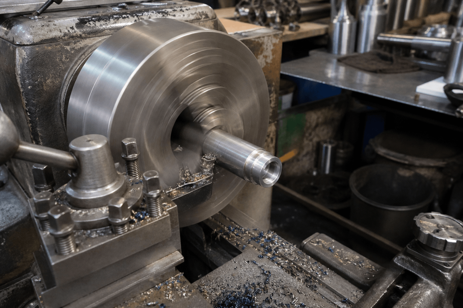
A manufacturing lathe holds and rotates a workpiece around a central axis while a cutting tool removes material. It is suited to shafts, bushings, pins, sleeves, collars, threaded components, and other parts organized around rotational geometry. A flat enclosure panel or bent bracket follows a different route through sheet metal fabrication.
What Is a Manufacturing Lathe?
When a buyer is reviewing a part drawing, the process decision often starts with a practical question: can the required surfaces be reached while the workpiece rotates? A manufacturing lathe grips material with a chuck, collet, faceplate, or another workholding device and rotates it around the spindle axis while the tool feeds along or toward the stock. This distinction matters when a project combines turned components with milled or fabricated parts.
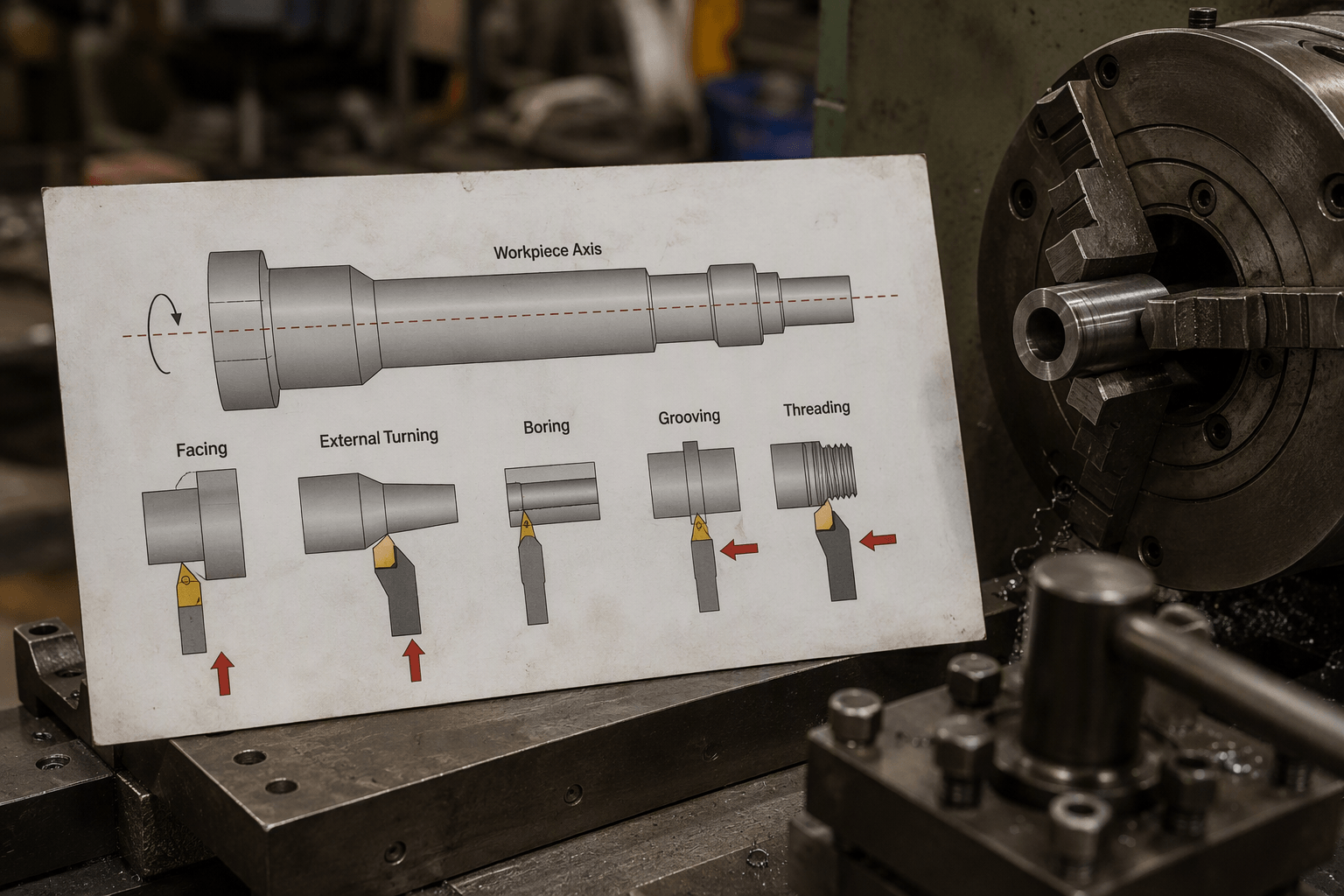
This arrangement can create outside diameters, shoulders, grooves, tapers, bores, threads, and faced ends. The lathe is the machine; turning is the principal cutting process performed on it. A CNC lathe uses programmed motion, while a manual lathe relies on operator-controlled movements. Not every CNC machine is a lathe, and turning does not always require CNC control.
Cutting tool → Controlled axial or radial feed
Rotation gives the lathe both its advantage and its boundary. Features centered on the spindle axis are naturally suited to turning, whereas broad flat profiles, off-axis features, bent sheet structures, and complete welded frames generally require other processes.
Which Parts Are Naturally Suited to Turning?
For an early design review, imagine the finished part rotating around its centerline. If most functional surfaces form cylinders, cones, circular grooves, or flat ends without moving away from that centerline, turning is likely to be a suitable primary process. Typical examples include shafts, pins, bushings, sleeves, collars, rollers, threaded studs, and cylindrical spacers.
| Required feature | Representative operation | Design consideration |
|---|---|---|
| Controlled outside diameter | External turning | Support and tool access are needed along the machined length. |
| Flat end or shoulder | Facing | The face may establish a length datum for later features. |
| Internal cylindrical diameter | On-center drilling and boring | Bore depth, chip removal, and tool clearance affect access and rigidity. |
| Reduced diameter or shoulder | Step turning | Relief, corner form, and mating-part clearance may need definition. |
| Tapered surface | Taper turning | Define the taper through related diameters and length, an angle, or a mating requirement. |
| Circular recess | Grooving | Width, depth, edge condition, and adjacent clearance influence access. |
| External or internal thread | Threading | Specify the thread system, size, pitch, fit, engagement length, and relief where needed. |
| Component separated from bar stock | Parting | The parted face and resulting burrs may require further attention. |
Common-axis geometry does not make every design straightforward. Long, slender shafts may deflect, thin sleeves can deform during clamping, and deep narrow bores can restrict tool access and chip evacuation. Interrupted surfaces also repeatedly load and unload the cutting edge.
Flats, side holes, pockets, and non-rotational contours may require additional workholding, repositioning, or a secondary process. A mostly cylindrical shaft with one cross-hole, for example, may be turned first and drilled afterward.
From Stock to a Finished Turned Part
A turned component usually begins as bar, tube, or another blank that only approximates the final form. The route depends on geometry, datum relationships, stock condition, feature access, and inspection requirements, so the sequence below is representative rather than universal.
- Select material and stock form. Material grade, condition, hardness, dimensions, and availability influence machining behavior and material use.
- Prepare the blank. Bar or tube may be sawed to length with allowance for facing, gripping, and parting. Sawing prepares stock; it does not create the controlled turned features.
- Establish workholding. The gripping method and unsupported length must provide access and adequate support. Clamping pressure and contact location matter especially for thin walls, soft materials, and restricted surfaces.
- Face and establish a reference. Facing creates an end surface that can support length measurements and later operations. Datum selection should reflect the drawing.
- Rough-turn the main geometry. Roughing removes most material from outside diameters, shoulders, or internal areas while retaining any allowance needed for finishing.
- Complete functional features. Finish turning, boring, grooving, taper turning, threading, or on-center drilling may follow. Order depends on rigidity, access, burr control, and feature relationships.
- Part off or reposition. A reverse face or gripped area may require another setup. Related features can sometimes remain in one setup, but one-setup production is not always possible.
- Deburr, clean, and inspect. Checks may cover diameters, lengths, shoulders, bores, threads, runout, concentric relationships, and surface condition as specified by the drawing.
Some parts require subsequent milling, off-axis drilling, grinding, heat treatment, deburring, or assembly. These are separate production stages rather than inherent lathe operations.
Match the Part Geometry to Turning, Milling, Sawing, or Sheet Metal Fabrication
When a component could follow more than one route, compare its dominant geometry and starting material. The processes are not interchangeable simply because each can remove or separate material.
| Routing question | Turning | Milling | Sawing | Sheet metal fabrication |
|---|---|---|---|---|
| Dominant geometry | Rotational surfaces sharing an axis | Flats, pockets, slots, holes, and non-rotational contours | Straight cutoffs and stock preparation | Flat patterns that are cut or punched, then bent, joined, or assembled |
| Starting form | Round bar, tube, forging, casting, or near-round blank | Block, plate, bar, casting, or prepared blank | Bar, tube, profile, plate, or sheet | Sheet or plate, sometimes with profiles or separate inserts |
| Cut relationship | The workpiece rotates while the tool feeds | A rotating cutter moves relative to a held workpiece | A blade passes through held stock | Material is cut or punched before forming and joining |
| Typical secondary work | Cross-drilling, milling flats, deburring, or assembly | Turning cylindrical references, drilling, or deburring | Turning, milling, forming, or welding after cutoff | Bending, hardware insertion, welding, finishing, or assembly |
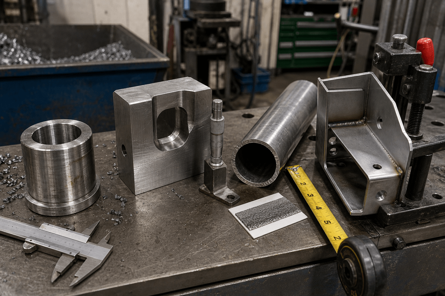
A cylindrical bushing with a concentric bore is a strong turning candidate. A rectangular block with an off-axis pocket points toward milling. Tube that only needs to be cut to length may require sawing. A bracket developed from a flat blank and bent along defined lines belongs in custom sheet metal fabrication.
A single product can use several routes: sawing may prepare a round blank, turning may establish diameters and threads, and milling or drilling may add a flat or cross-hole. A separate enclosure body may be cut, bent, joined, and fitted with the machined component. Route each component by its geometry and features.
Design Variables That Affect Lathe Manufacturability
Once a part appears suitable for turning, review the drawing for the conditions that affect workholding, access, inspection, and the number of required stages. These factors influence production economics without determining a universal outcome in advance.
| Factor | What to review | Why it matters |
|---|---|---|
| Material and condition | Alloy, hardness, heat-treated state, machinability, and stock availability | These affect cutting forces, chip behavior, tool wear, material use, and distortion risk. |
| Length, diameter, and wall thickness | Slender sections, thin walls, deep bores, and unsupported projection | The geometry may require different support, workholding, operation order, or cutting conditions. |
| Feature access | Groove clearance, bore depth, internal shoulders, corner radii, and tool approach | Restricted access can require another setup, tooling, or a design change. |
| Tolerance relationships | Diameters, bores, shoulders, threads, and faces sharing a datum or functional relationship | These relationships influence setup strategy and which features should be controlled together. |
| Surface requirements | Bearing, sealing, sliding, threaded, cosmetic, and noncritical surfaces | Finish requirements should be assigned by function rather than uniformly. |
| Workholding and secondary features | Grip areas, contact marks, deformation risk, flats, slots, cross-holes, and off-axis threads | These may add fixtures, repositioning, deburring, handling, and inspection. |
| Quantity | Prototype, recurring batch, or sustained production requirement | Quantity changes how setup, programming, fixturing, and tooling costs are allocated, but does not make unsuitable geometry appropriate for turning. |
Production economics extend beyond cutting time. Stock preparation, material utilization, programming, setup, fixtures, tool consumption, secondary machining, deburring, inspection, and handling may all contribute. Drawings are more useful when they identify critical dimensions and surfaces instead of applying the tightest requirement everywhere.
Inspection should follow the part’s function and datum structure. A mating diameter may need evaluation in relation to a shoulder, while a bore may need checking relative to an outside diameter. Threads, surface condition, runout, and concentric relationships should be assessed as specified. A defined quality control plan helps distinguish functional interfaces from general dimensions and cosmetic areas.
Where Turned Components Fit in Fabricated Assemblies
A lathe may produce individual components for a larger fabricated product without making the product body. Turned spacers can set panel separation, threaded bosses can create attachment points, sleeves can guide bolts or shafts, pins can locate moving members, and inserts can support press-fit or welded connections.
Consider a hypothetical control enclosure. Its panels could be cut from sheet, bent, joined, finished as specified, and assembled through the enclosure production route. Separate turned collars or threaded inserts might support a hinge, cable mechanism, or mounting interface. The panels remain sheet metal parts; only the rotational components are turned. See custom sheet metal enclosures for that product category.
Review the interfaces at assembly level. Drawings may need mating diameters, panel hole locations, thread callouts, press-fit conditions, weld requirements, edge clearance, orientation, and assembly space. A specified finish can affect a close-fitting interface, welding can move surrounding material, and press fitting can deform thin sections.
For a process-fit and drawing review, send part and assembly drawings with material and stock-form requirements, quantity, critical dimensions and tolerances, thread specifications, surface requirements, and prototype or repeat-production context. Identify which items are turned components and which are fabricated panels, brackets, or frame members. This gives the review a clear basis for routing and interface questions without assuming that every requirement must be produced in-house. Readers evaluating machined components can also review CNC machining.
Where RFQ Assumptions Create Cost and Production Risk
Many sheet metal fabrication problems begin before production starts. If drawings, tolerances, finish expectations, material grades, or assembly requirements are unclear, suppliers may quote based on different assumptions. That can make prices difficult to compare and may lead to rework, cosmetic rejection, assembly misalignment, or production delays later.
For OEM buyers, the goal is not simply to request the lowest price. The goal is to make sure each supplier is quoting the same manufacturing reality. Before confirming an order, clarify which dimensions are fit-critical, which surfaces are cosmetic, whether prototypes must match batch-production conditions, and how finished parts will be inspected.
Frequently Asked Questions
What manufacturing lathe details should buyers define before requesting a quote?
Buyers should define the functional requirement, drawing notes, critical dimensions, material or process expectations, and any inspection points related to manufacturing lathe. This helps suppliers quote the same manufacturing scope instead of making different assumptions.
How can RFQ details affect cost, fit, or lead time?
RFQ details can change tooling, forming, welding, finishing, inspection, or rework requirements. If buyers do not clarify it early, two supplier quotes may look comparable while covering different production risks.
Why should drawing requirements be reviewed before prototype approval?
drawing requirements may look acceptable on a single sample but become harder to control during batch production. Buyers should confirm whether the prototype reflects the same process, finish, and inspection conditions expected for production.
What inspection points matter most for manufacturing lathe projects?
Important inspection points usually include fit-critical dimensions, holes or mating areas, cosmetic surfaces, finish build-up, welded or formed features, and any dimensions that affect downstream assembly. These points should appear in the RFQ or drawing notes.
How can buyers reduce prototype approval risk before batch production?
Buyers can reduce risk by clarifying drawings, locking key material and finish assumptions, defining inspection timing, approving a representative sample, and confirming which dimensions or surfaces require tighter process control.
How can Yishang help review manufacturing lathe requirements?
Yishang can review drawings, RFQ notes, material requirements, tolerance expectations, finish details, samples, and assembly needs to identify unclear assumptions before quoting or batch production.