
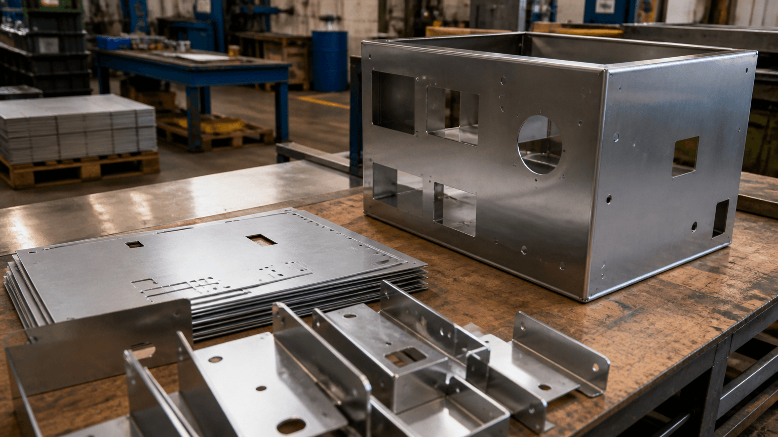
Metal works sheet metal generally means manufacturing components and assemblies from flat metal sheet through cutting or punching, bending, joining, finishing, inspection, and assembly. It is a coordinated family of processes rather than a single machine operation. A blank might be cut and bent into an enclosure panel, while several formed parts could be welded or fastened together to create a cabinet, rack, or frame.
Sheet Metal Work Within the Wider Metalworking Field
When evaluating an enclosure, bracket, cabinet, or equipment frame, the first question is whether its geometry can be created primarily from flat sheet. Sheet metal work describes work performed mainly on metal supplied in this form, while sheet metal fabrication is the more specific industrial term for converting the sheet into defined components or assemblies according to drawings, models, and manufacturing requirements.
Metalwork, normally written as one word when used as a noun, is broader. It can include sheet fabrication, machining, welding, forging, casting, structural metalwork, and decorative work. The two-word phrase metal work may simply describe work involving metal, while Metalworks or MetalWorks often appears in a company or brand name and does not identify a particular production method.
The practical distinction lies in the material’s starting form and the way the geometry is created. Sheet metal fabrication begins with flat sheet, then produces walls, panels, flanges, openings, and folded forms through cutting and bending. Welding, coating, assembly, and inspection may support the production route, but they remain separate joining, finishing, integration, and verification activities.
This route commonly applies to panels, brackets, cabinets, display racks, formed-sheet frames, custom sheet metal enclosures, and multi-part welded assemblies. It should not be confused with structural steel erection or with machining a three-dimensional part from solid stock.
From Drawing to Finished Assembly
A product rendering may show the intended shape, but it does not establish how the part should be manufactured. The route must be developed from the material, sheet thickness, geometry, tolerances, finish, quantity, and assembly requirements. Some parts need only cutting and bending; others also require joining, finishing, hardware installation, and final assembly.
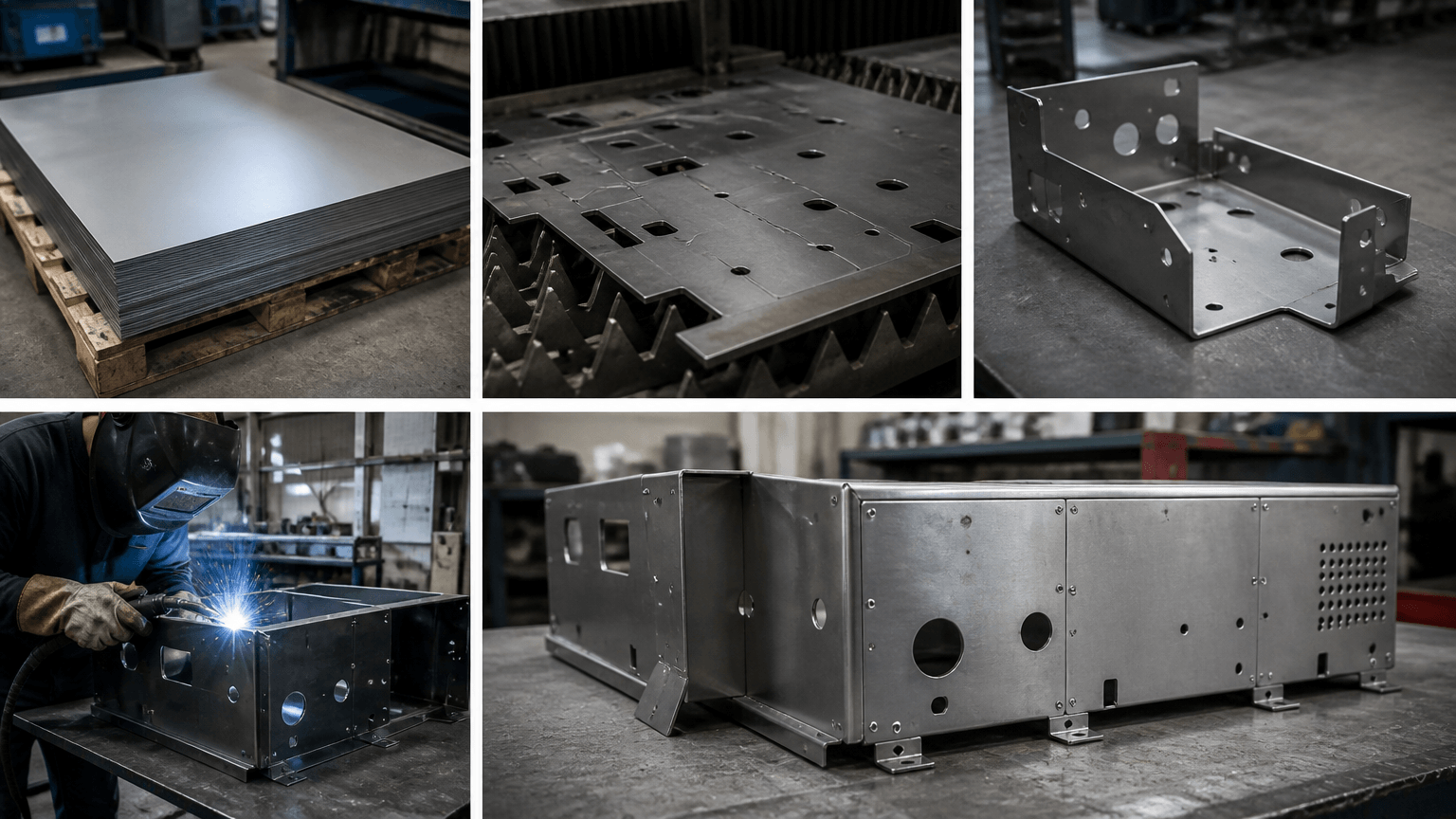
- Drawing and model review: The manufacturer examines dimensions, datums, tolerances, mating interfaces, visible surfaces, hardware, and assembly requirements. Any conflict between the controlled drawing and the available 3D model needs to be resolved before the part definition is released for production.
- Flat-pattern development: A formed component is unfolded into a blank that can be cut from sheet. Bend radius, bend allowance or deduction, springback, tooling, and bend geometry affect the developed dimensions. Detailed calculations depend on the selected material and production method rather than on a universal formula.
- Blank cutting or punching: Laser cutting creates external profiles and internal features in flat sheet. CNC punching uses tools to produce compatible holes, cutouts, repeated patterns, and certain formed features. These methods may be alternatives or complementary operations; the appropriate choice depends on the drawing and production context.
- Bending: The blank is formed along defined bend lines to create flanges, returns, channels, trays, covers, or box-like components. Bend sequence and tool access matter because one formed feature can obstruct a later bend. The metal bending stage converts a flat profile into a three-dimensional sheet component.
- Joining: Separate fabricated parts may be welded, fastened, or connected using specified hardware. Welding creates joints; it does not develop the flat pattern or form the complete product from sheet. Joint access, heat input, weld sequence, and distortion sensitivity require consideration where they affect fit or appearance.
- Surface finishing: Powder coating, polishing, or another specified finish may follow fabrication and joining. These operations alter or protect the surface rather than create the underlying sheet geometry. Visible faces, masked areas, color or texture requirements, polishing direction, and handling protection should be defined where relevant.
- Inspection: Verification can cover specified dimensions, hole locations, bend relationships, assembly interfaces, weld condition, and finish appearance. Inspection is a control activity applied at appropriate production stages, not a substitute for cutting, forming, or joining.
- Assembly and packing: Fabricated parts can be integrated with compatible hardware, machined items, extrusions, molded components, or other specified parts. Packaging should then reflect the product’s finish sensitivity, dimensions, assembly state, and transportation requirements.
What Each Fabrication Operation Contributes
Selecting a supplier or reviewing a proposed route requires more than confirming that several processes are available. Each operation creates a different result, and the output of one stage often becomes the input to the next. Including these operations in one fabrication route does not make them interchangeable or suitable for every material, geometry, thickness, tolerance, or quantity.
| Operation | Function | Key routing consideration |
|---|---|---|
| Laser cutting | Cuts profiles, slots, openings, and other features from flat sheet. | Material, thickness, feature geometry, edge requirements, and downstream operations affect suitability. |
| CNC punching | Uses tooling to produce holes, cutouts, repeated patterns, and compatible formed features. | Tool availability, feature spacing, sheet layout, and production quantity influence selection. |
| Bending | Forms angles, flanges, and folded walls along controlled bend lines. | Radius, flange geometry, tool access, springback, and bend sequence require review. |
| Welding | Joins separate components into a permanent part or assembly. | Material, joint design, access, cosmetic expectations, and distortion sensitivity matter. |
| Powder coating | Applies a coated surface finish after the required fabrication and preparation stages. | Color, texture, masked regions, visible surfaces, and acceptance requirements must be defined. |
| Polishing | Mechanically changes surface texture and appearance. | Base material, visible faces, directional grain, weld blending, and handling affect the result. |
| Assembly | Integrates fabricated parts with specified hardware or other components. | Mating interfaces, access, installation sequence, and shipment configuration need consideration. |
Common Products and Their Fabrication Routes
Product names provide a useful starting point, but they do not define a fixed process recipe. A single bracket may consist of one cut and bent blank, whereas a cabinet can contain multiple formed panels, welded sections, hinges, fasteners, and purchased components. The complete construction therefore needs to be reviewed before the route is assigned.
| Product category | Representative route | Main design considerations |
|---|---|---|
| Enclosures | Cut or punch, bend, install hardware, finish, and assemble | Openings, door fit, mating interfaces, mounting features, and cosmetic faces |
| Cabinets | Form multiple panels, join, finish, install hardware, and assemble | Frame alignment, door gaps, shelves, equipment interfaces, and installation access |
| Display racks | Cut and form components, weld or fasten, finish, and assemble | Stability, product supports, visible joints, handling, and shipment configuration |
| Formed-sheet frames | Cut and bend members, then join them into a larger structure | Squareness, mounting points, joint distortion, and equipment interfaces |
| Brackets | Cut or punch, followed by one or more bends | Hole-to-bend relationships, load direction, flange clearance, and mating parts |
| Panels | Cut or punch, optionally form edges, then apply the specified finish | Flatness requirements, cutout locations, visible surfaces, and mounting features |
| Welded assemblies | Fabricate separate components, fixture, weld, inspect, and finish as specified | Joint access, datum control, distortion, finishing access, and assembly sequence |
The actual routing must be confirmed from the drawing, material, finish, quantity, and required assembly state. Buyers evaluating custom sheet metal structures and assemblies should consider the complete product architecture rather than choosing a route based only on the cutting method.
Match the Part Geometry to the Manufacturing Route
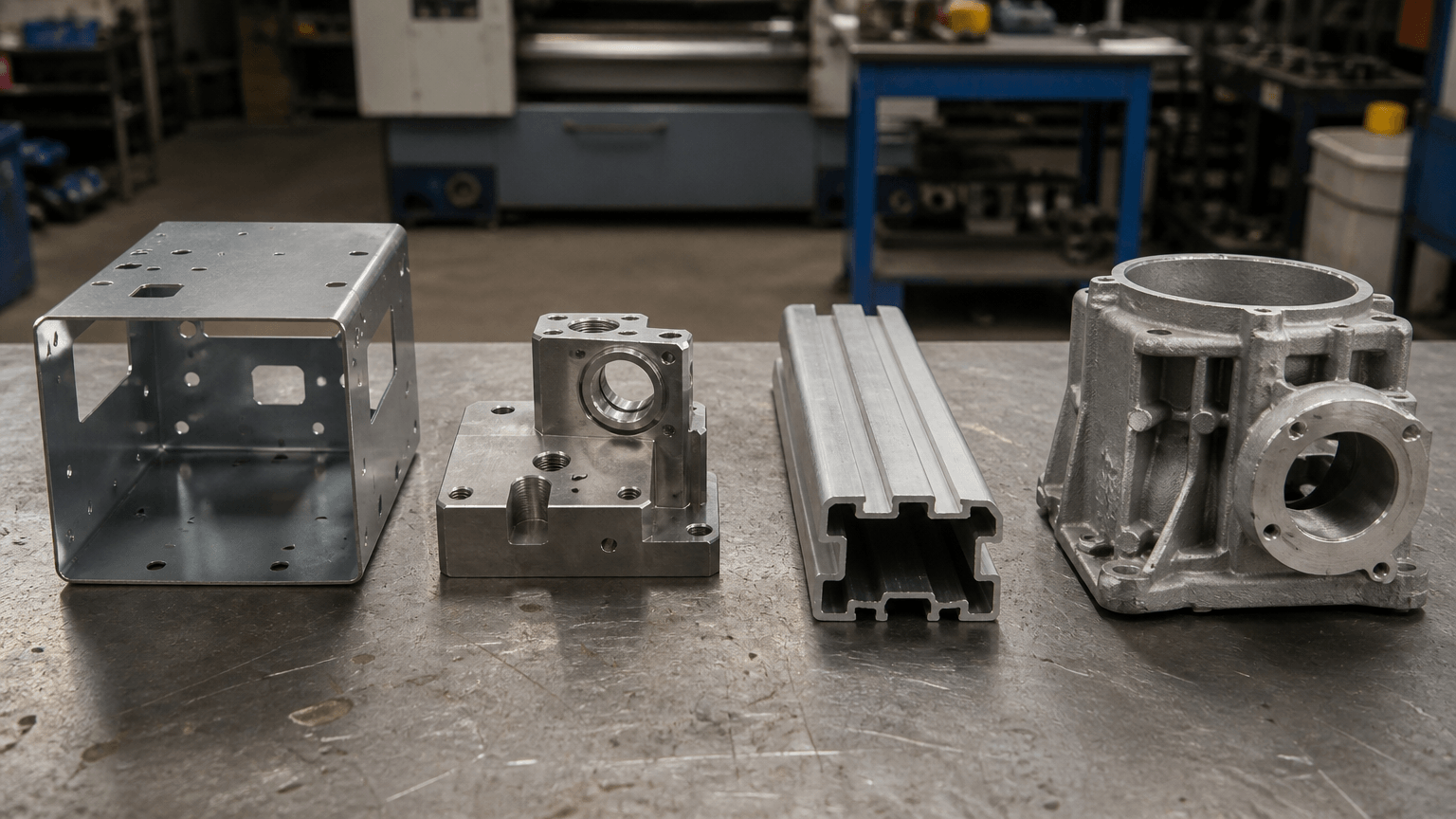
Sheet metal fabrication is a strong candidate when a product can be constructed from cut and formed walls of specified thickness. If the design instead depends on solid features, a continuous cross-section, cast forms, or molded polymer details, another process may be more appropriate. Many OEM products use a hybrid route, combining several manufacturing methods without treating them as a single operation.
| Process | Starting form | Geometry commonly associated with it | Process-selection signal |
|---|---|---|---|
| Sheet metal fabrication | Flat sheet | Panels, flanges, folded walls, brackets, boxes, formed frames, and built-up assemblies | The design can be divided into cut, bent, joined, and assembled sheet components. |
| CNC machining | Solid stock or another machinable workpiece | Pockets, bores, threads, shoulders, and other solid three-dimensional features | The geometry requires material removal or solid features that cannot be produced by bending sheet. |
| Extrusion | Material formed through a profile die | Long parts with a substantially constant cross-section | The same profile continues along the component’s length. |
| Casting | Molten material introduced into a mold | Integrated housings, ribs, bosses, and shapes that may be difficult to build from folded panels | Cast geometry and the production context justify mold or die development. |
| Injection molding | Polymer feedstock formed in a mold | Plastic shells, clips, ribs, bosses, and integrated molded details | The design requires polymer material, and molding tooling is appropriate for the project. |
For example, a fabricated enclosure may hold machined spacers, mount to extruded rails, or receive a molded cover. The sheet enclosure, machined spacer, extrusion, and molded cover retain separate process definitions; assembly determines how their interfaces fit together. Geometry that requires solid machined features can be reviewed through a separate custom CNC machining route.
Practical next step: If a design combines folded walls with solid bosses, profile rails, or molded details, review the interfaces before assigning the entire product to one process category.
Information Needed to Confirm Fabrication Feasibility
A product name, rendering, or photograph may communicate the concept, but it is not enough to confirm the manufacturing route. Material specification and sheet thickness establish the starting point because they affect cutting, forming, joining, weight, and finish compatibility. The selected material must also suit the product’s functional and service requirements.
A controlled 2D drawing should identify critical dimensions, datums, tolerances, mating interfaces, bend requirements, weld locations, cosmetic surfaces, finish, installed hardware, and assembly responsibilities. An available 3D model can help communicate geometry, but it does not replace the drawing requirements that govern manufacturing and inspection.
Prototype and expected production quantities can influence programming, nesting, tooling choices, fixturing, inspection planning, and whether flexible fabrication or a more dedicated production route is appropriate. Packaging requirements and the delivery destination also become relevant when a product has sensitive finishes, unusual dimensions, or a defined shipment configuration.
These factors must be considered together. A mating interface can affect bend control and inspection, while the selected finish may change how visible joints and contact areas are treated. Capability, timing, and commercial terms therefore require project-specific confirmation.
Request a process-fit and manufacturability review. Provide the controlled 2D drawing, available 3D files, material and sheet-thickness requirements, critical dimensions and tolerances, finish, welding, hardware and assembly requirements, prototype quantity, expected batch quantity, and delivery destination. The review can identify a likely sheet metal route and determine whether separately machined, extruded, cast, or molded components should also be considered. Final capability, timing, and commercial terms remain subject to drawing review.
Sheet Metal Terminology and Process Questions
These distinctions help buyers describe the required manufacturing route more accurately when discussing drawings, prototypes, tolerances, finishes, and production quantities.
Is it sheet metal work, sheet metal works, or metalwork?
“Sheet metal work” is the usual general term for work performed on sheet metal. “Sheet metal works” may refer to activities or facilities, or it may appear in a business name. “Metalwork” is the broader noun covering multiple ways of working with metal, while “MetalWorks” is often a company or brand name rather than a technical process.
Is a sheet metal worker the same as a welder?
Not necessarily. A sheet metal worker may cut, form, fit, assemble, or install sheet components. Some sheet metal workers also weld, but welding is a distinct joining discipline. A welder is not automatically responsible for flat-pattern development, punching, bending, finishing, inspection, or complete product assembly.
What can a sheet metal fabrication company produce?
Representative categories include enclosures, cabinets, panels, brackets, display racks, formed-sheet frames, covers, trays, and welded assemblies. Whether a specific company can manufacture a proposed product depends on the drawing, material, thickness, geometry, tolerances, finish, prototype or batch quantity, hardware, and assembly requirements.
How does sheet metal fabrication differ from CNC machining?
Sheet metal fabrication creates geometry mainly by cutting and forming flat sheet, followed by joining or assembly where required. CNC machining removes material from a workpiece to produce solid features such as pockets, bores, shoulders, and threads. A fabricated assembly may include a machined component, but the parts are still produced through separate processes and connected through defined assembly interfaces.