
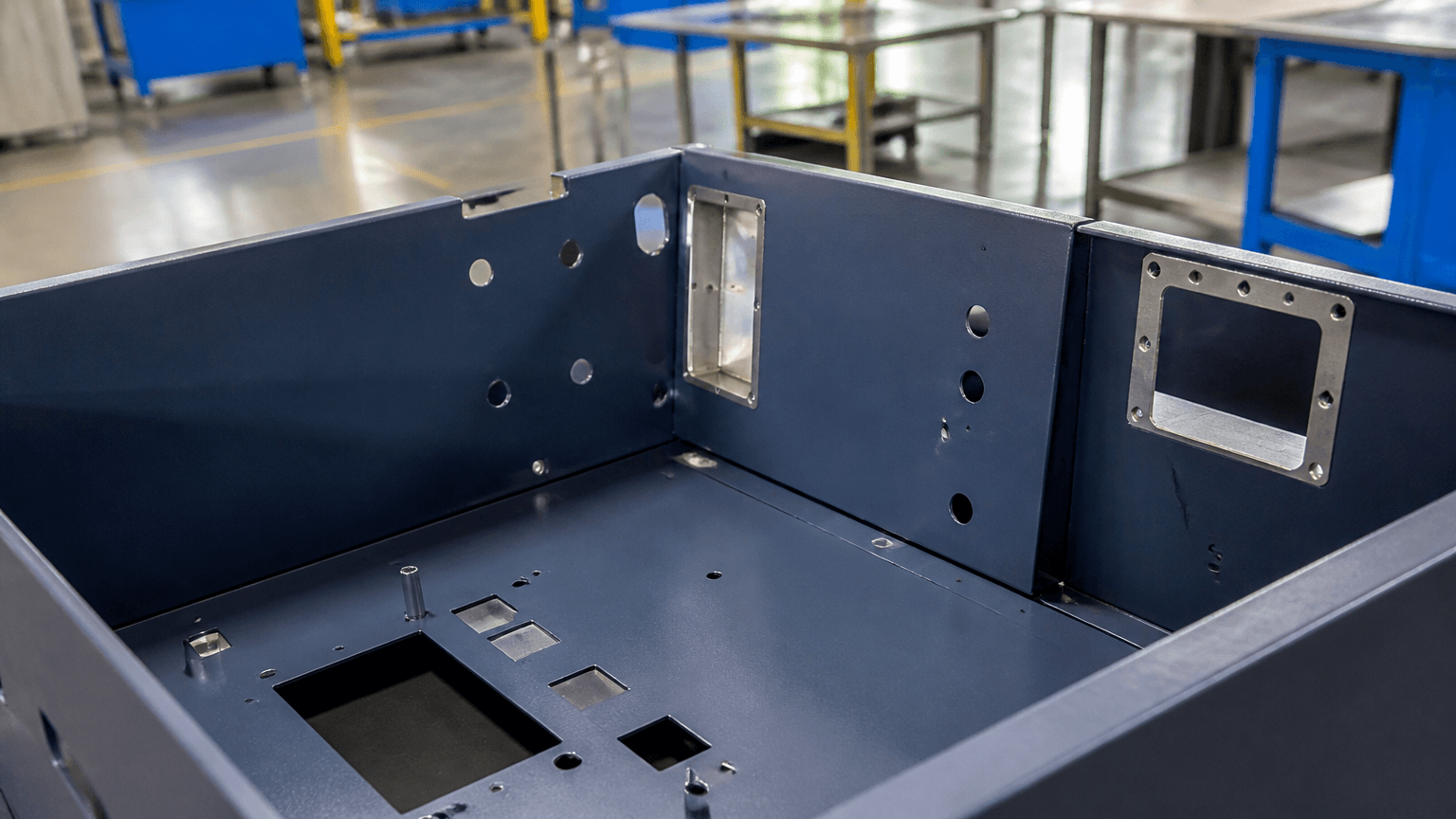
Direct answer: “Metal powder coated” normally means a fabricated metal part with a powder-coated finish: dry powder particles are electrostatically attracted to prepared metal and then heat-cured into a film. It does not mean a part formed from loose metal powder through powder metallurgy, and it is not a complete performance grade by itself.
The phrase “electro mechanical assemblies” is commonly written “electromechanical assemblies.” These assemblies combine structural parts such as enclosures, cabinets, frames, brackets, or welded panels with electrical or electronic hardware, fasteners, connectors, and grounding features. Powder coating is one finishing stage within that route; it does not define the electrical design or complete assembly specification.
Where Powder-Coated Metal Fits in an Electromechanical Assembly
For a fabricated-part route, the metal geometry is made first and the surface is finished afterward. Powder coating uses charged dry particles that are attracted to the prepared surface before heat melts and cures them. The finish therefore needs a defined substrate, preparation route, powder system, coating extent, appearance, and service environment.
| Term | What it describes | What still needs definition |
|---|---|---|
| Powder-coated metal | A formed or fabricated part with a cured dry coating | Substrate, preparation, powder, appearance, and boundaries |
| Liquid paint | A wet coating dried or cured on the part | Layers, drying route, repairs, and appearance |
| Plating | A deposited metallic layer on a conductive substrate | Function, coverage, thickness, and dimensional limits |
| Anodizing | An electrochemical surface conversion mainly associated with aluminum | Alloy, color, appearance, and masking |
| Galvanized or pre-coated metal | Material supplied with a zinc or other coating | Cut and weld areas, compatibility, and pretreatment |
| Powder metallurgy | A method of forming a part from compacted metal powder | Part material and forming specification, not surface finish |
These processes are not interchangeable. Adhesion, appearance, and corrosion resistance depend on the complete coating system and the service conditions. See surface-finishing options for custom powder-coated metal parts only after the required finish function is clear.
Fabrication-to-Finish Process Map
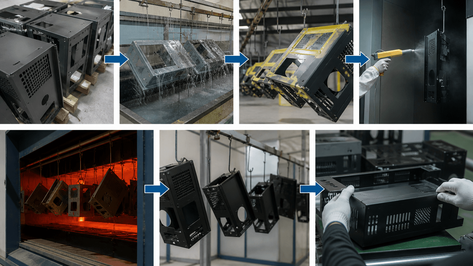
Laser cutting, CNC punching, bending, and welding create the fabricated part; powder coating is the subsequent finishing stage. A typical route for an enclosure, cabinet, frame, bracket, or welded assembly is:
- Fabricate the geometry. Cut, punch, bend, and weld the components according to the drawing.
- Set the pre-finish condition. Deburr features, address weld spatter and sharp edges, and resolve visible surface damage.
- Clean and pretreat. Oil, rust, fingerprints, dust, and residues must be addressed. Degreasing, rust removal, conversion treatment, abrasive blasting, or another route is selected for the substrate and its condition.
- Mask defined areas. Use plugs, caps, tape, or another method where threads, contact points, mating faces, or close-fit features require a coating limit.
- Apply the powder. Charged particles are sprayed onto the prepared surface. Orientation, edges, corners, and recesses affect access and coverage.
- Cure the coating. The schedule must match the powder system, part mass, geometry, and validated oven conditions; a universal recipe should not be assumed.
- Unmask and handle. Remove protection after curing and review rack or hook marks and handling damage.
- Inspect the result. Check agreed appearance, film thickness, dimensions, holes, threads, fit, coating limits, and performance requirements.
Galvanized or pre-coated sheet enters the route with a surface already present. It should not automatically be treated like bare steel or aluminum; compatibility, contamination, cut edges, welds, and pretreatment need review. For upstream context, see custom sheet-metal fabrication before finishing and sheet-metal enclosures with defined assembly interfaces.
Controlling Fit, Grounding, and Coating Boundaries
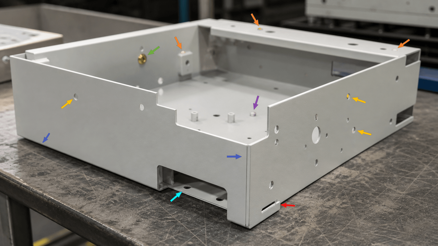
A finish can meet its visual requirement and still interfere with installation. The added layer may reduce clearance, affect thread engagement, change how a mating face seats, or interrupt electrical contact. The drawing should define the required condition for each functional zone rather than assuming that every hole or edge must be cleared.
| Zone | Possible risk | Define and inspect |
|---|---|---|
| Threads and inserts | Reduced clearance or difficult fastener engagement | Mask, protect, or define the accepted condition; check with specified hardware |
| Mounting and connector holes | Changed fit for screws, pins, standoffs, or connectors | State whether coating remains; verify assembly fit |
| Grounding points | Coating may interrupt metal-to-metal contact | Identify the contact path and check continuity where applicable |
| Mating and sliding faces | Changed seating, friction, or movement | Keep coated, mask, or specify a limit; verify the interface |
| Folded and internal faces | Limited spray access or unclear concealed coverage | Clarify required coverage and inspect representative areas |
| Welds, edges, and recesses | Spatter, coverage differences, or local texture variation | Set preparation and appearance expectations |
| Rack or hook areas | Small uncoated marks or handling impressions | Locate acceptable marks in a hidden area or define the allowed condition |
Useful drawing instructions include keep coated, mask, remove coating after cure, and allow coating within this range. Confirm the boundaries during first-article inspection.
Powder-Coated Metal Finish Brief: What to Define Before Quote, Sample, or Batch Production
“Black powder coat” communicates intent but is rarely a complete production requirement. Use this worksheet to give engineering, purchasing, and the finishing supplier the information needed to assess feasibility, masking effort, inspection, cost, and timing.
| Field | Production-ready information |
|---|---|
| Part and substrate | Base metal, material grade where required, sheet thickness, dimensions, and weld condition |
| Coating extent | All surfaces or identified visible, internal, folded, and concealed faces |
| Powder and appearance | Powder or coating-system reference, color code or approved sample, gloss, texture, and appearance level |
| Preparation | Cleaning or pretreatment expectation, weld-spatter condition, edge requirements, and compatibility checks |
| Film thickness | Target or agreed requirement, measurement locations, and inspection method |
| Functional boundaries | Threads, holes, grounding points, mating faces, sliding areas, inserts, and rack-mark limits |
| Environment and tests | Indoor or outdoor exposure, moisture, chemicals, heat, and required performance tests |
| Acceptance method | Color, gloss, texture, adhesion, visible defects, edge coverage, dimensions, fit, and sample comparison |
| Production and logistics | Part size, quantity, rack or oven constraints, masking complexity, packaging, timing, batch matching, and rework |
Part size can interact with rack handling and oven constraints. Quantity can influence setup and batch matching, while complex masking, unmasking, rework, and packaging add handling considerations. If multiple panels, cabinets, or brackets must match, approve a representative sample or reference panel for color, gloss, texture, coverage, and acceptable variation before batch production.
Application Decision Matrix
Choose the route by substrate, geometry, layer function, appearance, repair needs, and heating constraints—not by unsupported claims about cost or durability.
| Finish route | May fit when | Boundary to validate |
|---|---|---|
| Powder coating | Fabricated metal has accessible surfaces, defined appearance, and can accommodate heat curing | Compatibility, preparation, cure, masking, coverage, and interfaces |
| Liquid paint | A wet-applied system, field-repair route, or temperature-sensitive process is needed | Layers, drying or curing, overspray, repair, and appearance |
| Plating | A thin metallic or conductive, wear, or contact function is required | Chemistry, coverage, dimensional change, and contact areas |
| Anodizing | An aluminum part needs electrochemical conversion rather than an applied powder layer | Alloy, color consistency, masking, and surface behavior |
| Galvanized or pre-coated substrate | The material specification already includes a zinc or other coating | Cut edges, welds, contamination, pretreatment, and compatibility |
First-Article Release and Batch Control
Approve the first finished part for more than color. It should show that the appearance, drawing revision, coating boundaries, dimensions, and electromechanical interfaces work together.
- Record the material, thickness, fabrication revision, powder reference, preparation route, and masking instructions.
- Compare color, gloss, texture, coverage, welds, edges, recesses, and rack marks with the approved sample under agreed conditions.
- Check dimensions, holes, threads, inserts, mating faces, sliding features, grounding areas, and assembly fit.
- Measure film thickness at agreed locations and use agreed methods for adhesion, hardness, corrosion resistance, or other tests when required.
- Review masking transitions, packaging, handling marks, and any damage to visible surfaces.
- Define how nonconforming parts, rework, finish variation, and approval changes will be handled.
Repeatability depends on consistent substrate preparation, powder identity, cure control, rack orientation, masking, and batch approval. If a defect appears, trace the route before changing the specification: review contamination and cure for adhesion problems; geometry, access, and orientation for uneven appearance; boundaries and masking for blocked interfaces; and powder identity, reference conditions, and batch handling for color variation.
Project-specific finish review: For an OEM or ODM custom sheet-metal project, request a review of the fabrication route, powder-coating requirements, assembly interfaces, prototype stage, and batch handoff. Yishang has more than 26 years of experience and exports to more than 50 countries. Share:
- 2D drawing or 3D model, base metal, specified material grade, thickness, dimensions, and relevant tolerances
- Quantity, prototype or batch stage, and target timing
- Color reference or approved sample, gloss, and texture requirements
- Coated and uncoated areas, threads, grounding points, mating surfaces, and masking instructions
- Service environment plus required inspection or performance tests
Confirm the specific in-house process scope and production arrangement for the project. Quality-control planning for finished metal products can be included in the prototype and first-article discussion.
FAQ: Powder-Coated Metal in Electromechanical Assemblies
Should threads, mounting holes, and grounding points be masked?
It depends on their function and the drawing. Some holes may remain coated, while threads, grounding contacts, or close-fit features may need masking or a defined clear area. Check the finished interface with the specified hardware.
Why do bends, welds, edges, and recesses look different?
Weld profile, edge geometry, preparation, spray access, orientation, and local film build can vary across a part. Set the appearance level and inspect representative areas on the prototype or first article.
Can a coated part be drilled, bent, or machined afterward?
Post-finish work can damage the coating, expose the substrate, change fit, or require repair. Plan the work before coating where possible; otherwise define the affected area, repair route, and acceptance condition.
How can batches maintain color, gloss, and texture matching?
Approve a physical sample or reference panel and record the powder reference, gloss, texture, inspection conditions, and acceptable variation. Discuss batch matching when separate parts must appear consistent.
Does powder coating automatically protect metal outdoors?
No. Performance depends on the substrate, preparation, powder system, cure, boundaries, and exposure to moisture, chemicals, heat, and handling. State the service environment and required tests instead of relying on the finish name.