
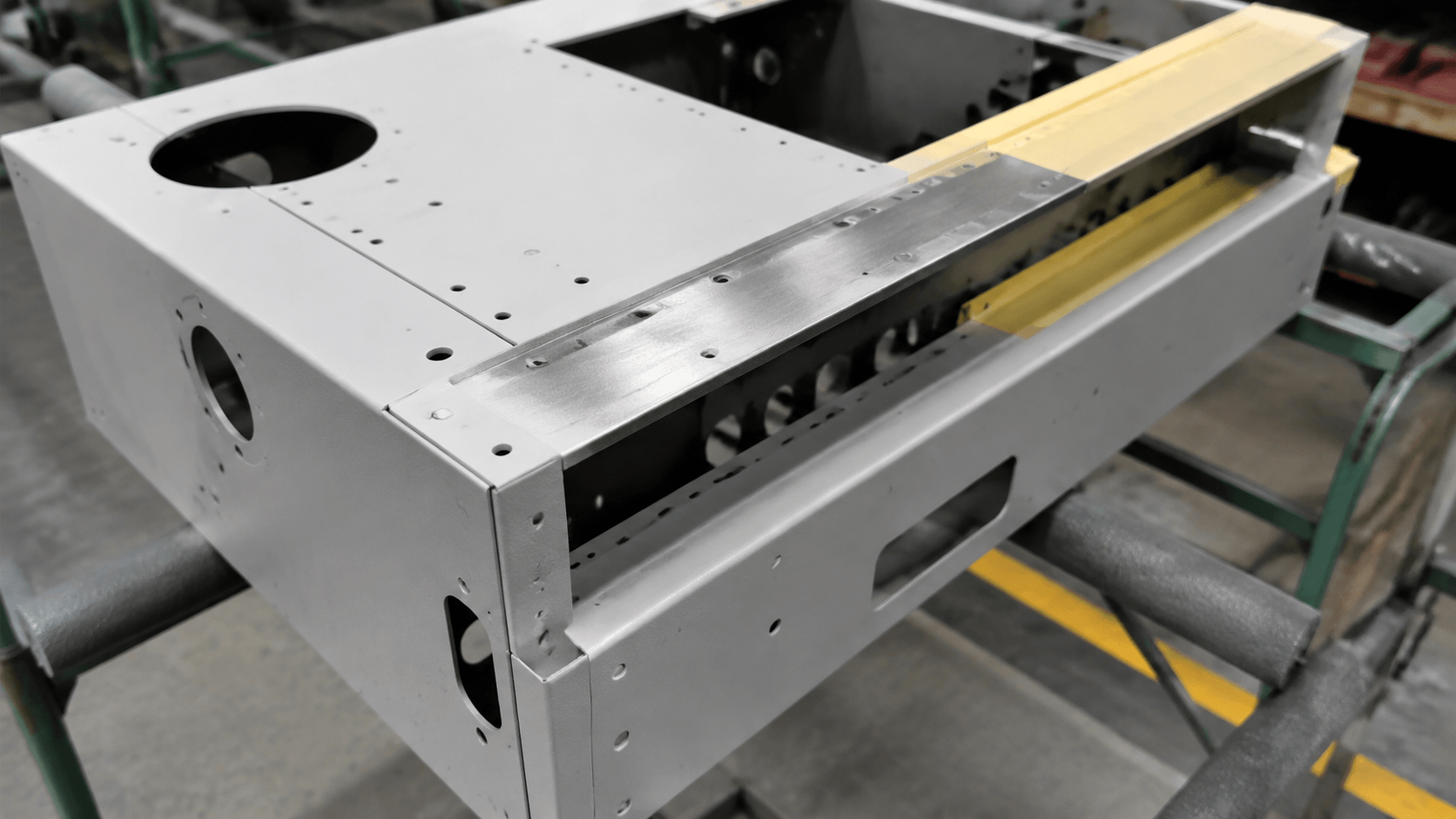
In OEM usage, “metal powder coated” means a fabricated metal part has received a dry powder surface finish that is electrostatically applied and typically heat-cured. The phrase alone does not define the substrate, appearance, protected areas, or acceptance criteria needed to release the part for production.
For a buyer, powder coating manufacturing usually describes the production route for a finished coated item rather than the manufacture of the powder itself. The item may be a custom sheet metal part, enclosure, cabinet, display rack, frame, bracket, or welded assembly, but the supplier still needs to know its fabricated delivery state and which surfaces must remain visible or functional.
What “Metal Powder Coated” Means on an OEM Part
If you are comparing quotations for an enclosure, frame, or welded assembly, “metal powder coated” identifies the final surface state but leaves several production decisions open. The part may already be cut, formed, joined, machined, or fitted with inserts before the coating stage, and each condition affects preparation, masking, coverage, and assembly.
Dry powder is deposited on the prepared metal surface. The part is normally grounded while the powder particles receive an electrostatic charge, attracting them to accessible faces and edges.
Heat typically melts and cures the deposited layer. The appropriate cure window depends on the powder system, substrate, part thickness and mass, and geometry, so a universal temperature or time should not be placed on every drawing. Film build and edge coverage also depend on the application setup and part features.
This finish route is different from raw sheet metal, liquid-painted metal, electroplating, anodizing, or galvanizing. Those are separate material or finishing choices for particular applications. It is also different from powder metallurgy, where metal powder is used to form the component itself. “Metal powder coated” remains incomplete until the buyer defines the finish and its functional boundaries.
Where Powder Coating Sits in the OEM Fabrication Route
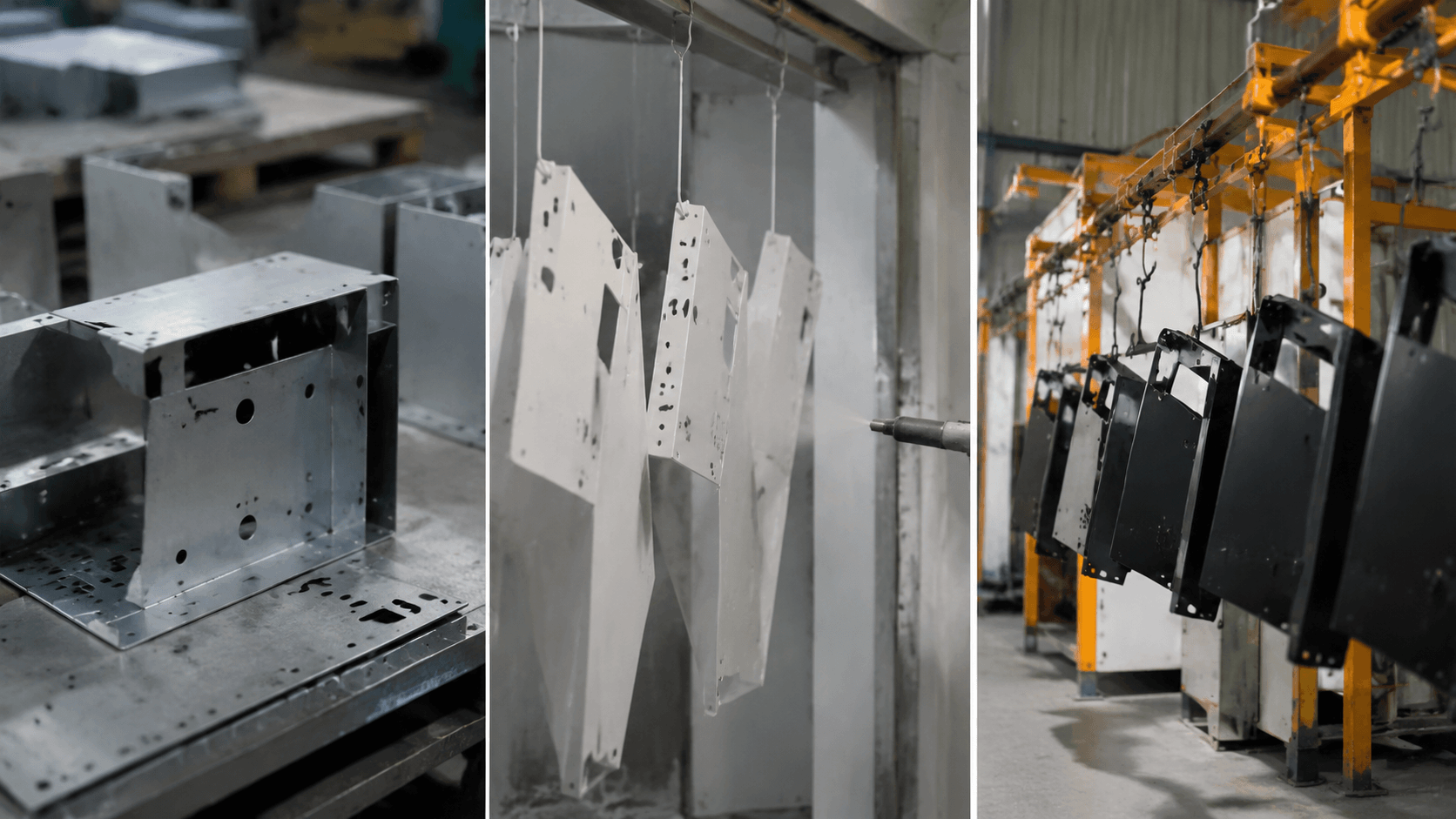
Powder coating normally follows the main fabrication and surface-preparation stages and precedes final assembly. That sequence matters because oil, weld residue, sharp edges, and unreviewed interfaces can become finish defects or fit problems after the part has already entered the coating line.
- Cutting and forming: Laser cutting or CNC punching creates the sheet-metal blank. Bending then forms flanges, returns, panels, and other features. These operations establish the holes, slots, datums, and edges that coating must accommodate.
- Machining and joining: CNC turning or milling may create a machined component, insert, or interface; it is distinct from sheet metal fabrication. Welding joins fabricated pieces into an assembly. If a machined part is integrated into the assembly, define whether it is coated separately, installed after coating, or protected during coating.
- Pre-finish fabrication review: Weld spatter, sharp edges, uneven seams, grinding residue, and other surface conditions should be addressed before finishing. Coating does not correct a fabrication or drawing-revision error.
- Cleaning: Oil, rust, scale, handling dirt, and weld-related contamination can affect adhesion and appearance. Degreasing and derusting or scale removal are selected according to the substrate and part condition.
- Pretreatment and drying: Phosphating, blasting, or another substrate-appropriate preparation may be used. The part must be dry before powder application, including areas around seams, recesses, and drainage paths.
- Powder application and curing: The prepared part is grounded and powder is applied electrostatically. The deposited layer is then typically melted and cured with heat. Film-build control, edge coverage, and the cure window influence finish consistency and may affect fit or dimensional behavior.
- Inspection and assembly: Masking is removed, protected interfaces are checked, and the coated part is inspected before hinges, fasteners, inserts, or other final assembly items are installed.
Mild steel, aluminum, stainless steel, and galvanized steel may require different cleaning and pretreatment decisions. A route suitable for one substrate should not be assumed for another; review the material together with the surface finishing options for custom powder-coated metal.
Coating-Fit Review for OEM Parts and Assemblies
The route can suit custom sheet metal parts, metal enclosures and cabinets, display racks, frames, brackets, and welded assemblies when geometry and interfaces are reviewed in advance. A coating that is straightforward on an open panel may require more preparation, masking, or inspection on a deep enclosure or densely welded frame.
| Part condition or feature | Risk to review | Drawing or RFQ action |
|---|---|---|
| Product geometry and visible surfaces | Panels, flanges, doors, rack members, and brackets may have different appearance expectations. | Mark customer-facing surfaces, edges, welds, and internal areas. |
| Substrate and thickness | Alloy or grade, thickness, heat-up behavior, pretreatment, and film build may differ. | State the exact substrate, thickness, revision, and fabricated state. |
| Welded areas and contamination | Spatter, sharp weld profiles, residue, or inconsistent surfaces can affect coverage and appearance. | Identify cosmetic weld areas and required cleanup before coating. |
| Edges, seams, recesses, and cavities | Sharp edges and internal corners may receive different coverage from broad faces; deep cavities may have limited access. | Define which internal surfaces are visible, functional, or exempt, and review edge treatment. |
| Holes, slots, and threads | Coating build-up can reduce clearance or interfere with fastener engagement. | Mark critical features for masking, protection, or post-coating inspection. |
| Mating faces, grounding points, and machined interfaces | Coating on a contact surface may prevent fit or electrical contact. A machined component may need a separate finish route. | Define no-coat boundaries and whether the component is installed before or after coating. |
| Part size, orientation, and hangers | Handling and hanger locations must work with the available coating equipment; contact points may leave marks or uncoated areas. | Provide overall dimensions, hanging points, orientation, and acceptable contact locations. |
| Batch quantity and masking complexity | Many masks, segregated batches, color changes, and tight reference-sample control can increase processing effort and affect scheduling. | State prototype quantity, expected batch quantity, masking count where known, and consistency expectations. |
For an enclosure or cabinet, distinguish the external finish from the inside of the box, door edges, hinge areas, and grounding points. These details matter when specifying powder-coated sheet metal enclosures that must fit adjacent components after finishing.
Build a Complete Drawing or RFQ Callout
A note such as “metal powder coated, black” leaves the fabricator to choose or assume several requirements. Use the following fields to make the part reviewable without prescribing an unsuitable system or making an unsupported performance claim.
| Callout field | Information to define |
|---|---|
| Part identity and substrate | Drawing revision, material grade, thickness, overall dimensions, and whether delivery is formed, welded, machined, or partially assembled. |
| Coating system and service context | Powder system if already selected, plus the service environment or required performance conditions when known. Otherwise request supplier review. |
| Color and appearance | Color reference or approved physical sample, gloss level, texture, matte or metallic requirement, and visible-surface expectations. |
| Visible surfaces | Customer-facing faces, edges, welds, internal areas, and any locations where hanger or handling marks require separate acceptance. |
| Film build | Target thickness or an agreed range when dimensional, insulating, appearance, or performance control requires it. Do not assume one value suits every location. |
| Protected zones | Threads, holes, mating faces, grounding points, labels, inserts, hinge seats, and areas to be masked, stripped, or left uncoated. |
| Critical post-coating dimensions | Hole and slot requirements, thread engagement, mating clearances, datums, and assembly dimensions that must be checked after finishing. |
| Inspection and batch basis | Viewing conditions, approved-sample method, acceptable visual variation, thickness locations, quantity, batch segregation, and any agreed performance test. |
Replace the phrase “metal powder coated” with five coordinated callouts
Use this compact block in a drawing handoff or technical inquiry:
- Substrate: [grade, thickness, revision, dimensions, fabricated delivery state]
- Coating appearance: [system if known, color reference or sample, gloss, texture, visible surfaces]
- Protected zones: [threads, holes, mating faces, grounding points, labels, hinges, assembly interfaces]
- Critical dimensions: [post-coating clearances, hole and slot requirements, thread and fit checks]
- Inspection basis: [sample reference, viewing conditions, thickness locations, appearance limits, agreed tests, batch rules]
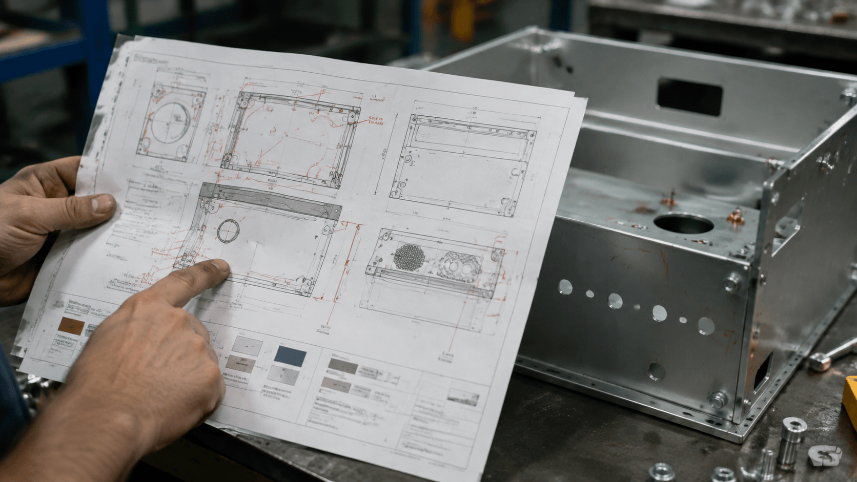
For an early project review, attach the worksheet to a 2D drawing, 3D CAD file, or marked-up part document. The custom sheet metal fabrication for powder-coated parts should be reviewed together with cutting, bending, welding, machining interfaces, finishing, and assembly requirements rather than treated as a finish note added at the end.
First-Article and Batch Approval
Approval should cover function as well as color. A representative first article should reflect the geometry, welded areas, recesses, visible surfaces, protected zones, and assembly interfaces expected in the production batch.
- Lock the reference: Confirm the drawing revision, substrate, finish callout, masking plan, hanging orientation, and critical interfaces.
- Approve the sample: Compare color, gloss, texture, and general appearance against the agreed physical or documented reference under the agreed viewing conditions.
- Check coverage: Inspect visible surfaces, edges, seams, recesses, and internal areas for incomplete coverage, defined edge problems, contamination, bubbles, peeling, or other agreed defects.
- Measure film build: Take thickness readings at agreed locations. One reading should not be treated as representative of the entire part.
- Verify function: Check masked threads, holes, grounding points, mating faces, hinges, fasteners, and other interfaces. Perform dimensional, fit, and assembly checks after coating where build-up could affect use.
- Apply agreed tests: Use adhesion, cure, corrosion, or other performance tests only when the buyer and supplier have agreed on the method and acceptance basis.
- Release the batch: Record the approved sample, appearance reference, inspection locations, acceptable variation, and batch-control requirements for later comparison.
- appearance and coverage are approved against the reference;
- edges, welds, recesses, and hanger areas have been reviewed;
- thickness locations and critical dimensions are documented;
- protected interfaces remain usable;
- the first-article reference and any agreed tests are recorded.
For an OEM or ODM project review, send the 2D drawing, 3D CAD file, or marked-up part document; substrate grade and thickness; part dimensions; current fabrication stage; prototype and expected batch quantities; color reference or physical sample; gloss; texture; visible-surface requirements; no-coat zones; service environment; and inspection requirements.
Yishang can review cutting, bending, welding, powder coating, machining interfaces, and assembly as linked stages before prototype or batch production. This review helps identify masking, coverage, fit, and approval risks early. Yishang supports OEM and ODM projects, has more than 26 years of custom metal manufacturing experience, and exports to more than 50 countries. Its quality control and inspection for finished metal products information can support discussion of an agreed approval basis.
In short, “metal powder coated” is a starting label, not a complete manufacturing specification. If it is the only finish note on your drawing, use the five-callout worksheet and request a technical review before committing to a prototype or production batch.
Frequently Asked Questions
These questions commonly arise when an OEM buyer moves from a general finish description to a drawing, prototype, or batch-production requirement.
Is metal powder coated a material description, a surface finish, or a manufacturing process?
It primarily describes the finished surface state and implies a finishing process. It does not identify the base metal and does not mean powder metallurgy, where powder forms the component itself.
Does powder coating cover the inside of an enclosure, holes, edges, and threaded features?
Not automatically. Access, geometry, application angle, pretreatment, and masking determine coverage. Deep cavities, holes, and threads may require separate review or protection.
Can any metal substrate be powder coated, or do different metals require different preparation?
Substrate suitability and preparation are not universal. Aluminum, stainless steel, mild steel, and galvanized steel may require different cleaning and pretreatment routes, so state the exact material.
Can powder coating change the fit of threads, mating surfaces, holes, or close-clearance assemblies?
Yes. Film build can reduce clearance, affect thread engagement, or cover an electrical contact. Identify these interfaces and check them after coating.
What should an OEM buyer send when requesting a powder-coated metal part, enclosure, frame, or welded assembly?
Send the drawing or CAD file, substrate, thickness, dimensions, fabricated state, prototype and batch quantities, color or approved sample, gloss, texture, visible surfaces, protected zones, service environment, and inspection requirements.