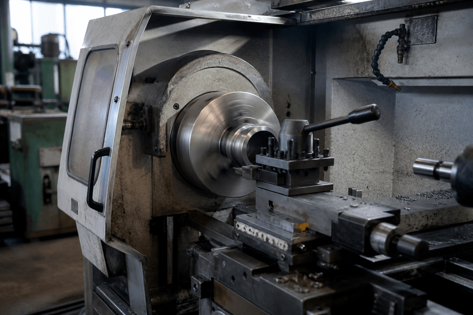
An industrial machinery lathe rotates a workpiece around a spindle axis while a controlled cutting tool removes material. This process is suited to predominantly rotational parts such as shafts, pins, bushings, sleeves, rollers, and threaded components.
When evaluating a machine for a drawing or production plan, first determine whether the part is fundamentally rotational and whether its diameter, length, bar size, features, and quantity fit the proposed configuration. Milling rotates the cutter to produce prismatic features, while laser cutting and punching profile sheet and bending forms it. These processes may contribute parts to the same machine assembly, but they are not forms of turning. Industrial lathes also differ substantially: the category includes manual engine and toolroom lathes, teach-in machines, CNC lathes, and multi-axis turning centers.
The Operating Principle of a Metal Lathe
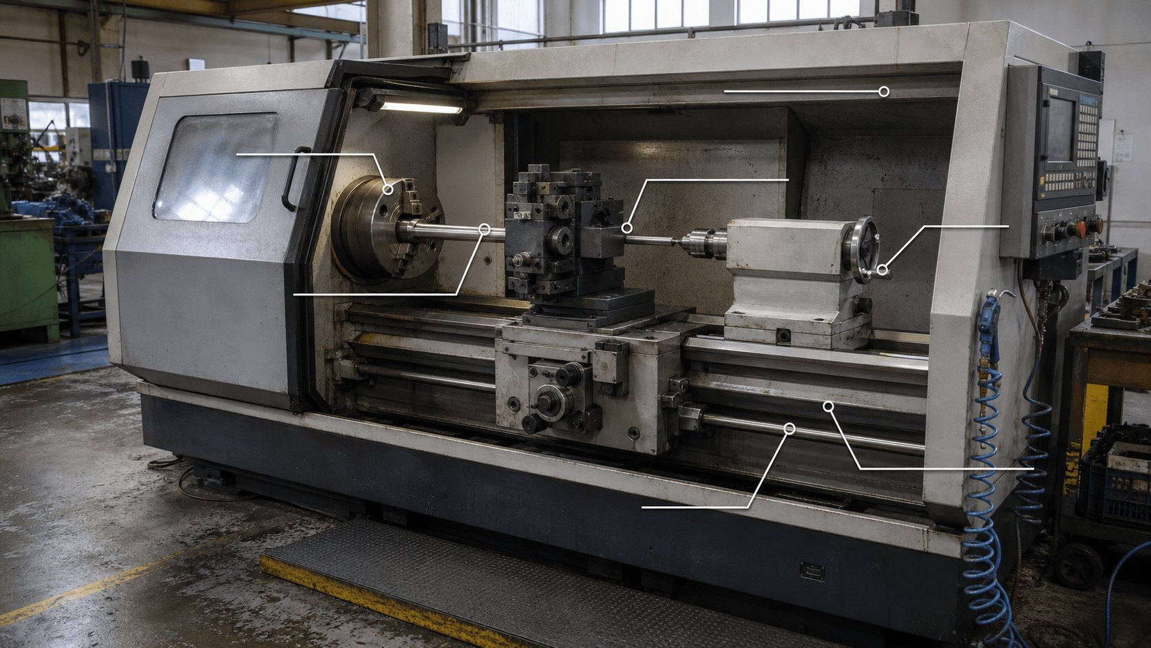
For a buyer reviewing a shaft, bushing, roller, or threaded component, the central question is whether the required features can be generated through workpiece rotation and controlled tool movement. A lathe holds the workpiece in a chuck, collet, faceplate, or between centers. The spindle rotates it while the cutting tool moves parallel to or across the spindle axis.
Depending on the machine, the tool may be carried by a manual toolpost, carriage, indexed turret, or powered tool station. A stepped shaft may combine outside diameters, shoulders, grooves, threads, and an axial bore. A bushing may require related outside and inside diameters. Tapers and contours are possible when the machine provides the necessary tool motion.
- Turning: The rotating workpiece is cut to produce cylindrical, tapered, faced, grooved, bored, or threaded features.
- Milling: A rotating cutter produces flats, slots, pockets, hole patterns, and other prismatic or indexed features.
- Sheet metal fabrication: Cutting creates flat profiles, bending forms panels and flanges, and welding joins prepared components into structures.
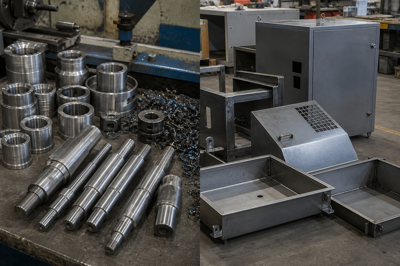
A turned component and a fabricated machine panel can belong to the same equipment assembly without sharing a manufacturing route. Their drawings, datums, tooling, joining methods, finishes, assembly requirements, and inspection plans should reflect the process used for each part.
Lathe Categories by Control and Production Role
Machine category narrows the initial search, but production volume, changeover frequency, operator involvement, and feature complexity determine which category deserves closer evaluation. The category name alone does not establish whether a particular model can produce the drawing.
| Configuration | Control and tooling | Typical application pattern | Point to verify |
|---|---|---|---|
| Manual engine lathe | The operator sets speeds and feeds, positions and changes tools, and checks dimensions | Repair work, one-off parts, maintenance tasks, and straightforward low-volume turning | Part support, operator access, feeds and speeds, and machine condition |
| Toolroom lathe | Usually manual, with versatile setup and controlled tool movement | Prototypes, tooling, development parts, and varied small batches | The toolroom label does not establish accuracy, condition, or drawing suitability |
| Teach-in lathe | Conversational programming or recorded sequences combined with manual flexibility | Changing batches and repeat work that benefit from stored cycles | Programming method, available cycles, tool arrangement, and control limits |
| CNC lathe | Programmed axis motion with indexed tooling and repeatable machining cycles | Recurring parts with multiple diameters, grooves, bores, or threads | Programming effort, workholding, tooling capacity, and production quantity |
| Multi-axis turning center | CNC turning with possible live tooling, C-axis or Y-axis motion, a sub-spindle, and handling equipment | Complex turned parts, bar-fed production, back-working, and selected non-round features | The axes, travels, tool orientations, spindle functions, and automation included on the model |
Manual engine and toolroom lathes retain direct operator involvement, which can suit repair or development work with frequent setup changes. A teach-in machine can store or generate repeatable cycles while retaining aspects of the manual operating model.
CNC becomes more relevant as repeat quantity, feature count, or the need for consistent sequencing increases. A turning center may consolidate turning with selected drilling or milling operations, but live tooling does not make it equivalent to a machining center. Tool orientation, axis travel, workholding access, and feature geometry determine whether a secondary operation is practical.
Features Produced by Turning
During drawing review, operation names help identify the required tool movements, but they do not confirm that every lathe can perform the work. Feasibility depends on machine configuration, material, workholding, tool access, clearance, and the complete operation sequence.
- Facing
- The tool feeds across the end of the rotating workpiece to create a flat end face or establish length.
- External turning
- The tool travels along the spindle axis to reduce outside diameter or form shoulders. Controlled changes in position can generate tapers or contours.
- Boring
- A boring bar enlarges or finishes an existing internal hole. Depth, tool overhang, access, and chip evacuation constrain the setup.
- Drilling
- A drill aligned with the spindle axis creates an axial hole. It may be mounted in a tailstock or turret.
- Threading
- Coordinated feed and spindle rotation generate an internal or external helical thread. Tooling, pitch, thread form, relief, and access must suit the part.
- Grooving
- A narrow tool creates an internal or external recess, such as a relief or retaining-ring groove.
- Parting
- A tool feeds radially into the stock to separate a component from bar or other work material.
Conventional turning primarily produces axially symmetric geometry. Flats, keyways, radial holes, off-center holes, and slots require another tool orientation. A turning center may produce selected non-round features with suitable live tooling and axis control; otherwise, the part needs a separate milling or drilling operation. A sub-spindle may support back-face work after transfer, subject to workholding and access.
Grinding may follow turning when the final dimensional or surface requirements call for it. These are sequential operations, not interchangeable processes. See custom CNC machining for sample and repeat production for information about adjacent machining routes.
Reading Capacity Beyond the Catalog Numbers
A catalog capacity can screen out an unsuitable machine, but it cannot confirm that a quoted setup will fit. Buyers must account for the workpiece, chuck, jaws, tools, supports, and chip-clearance envelope using the current datasheet for the exact model and options.
| Specification | Meaning | Application consequence |
|---|---|---|
| Swing over bed | The largest theoretical diameter that can rotate above the bed | Practical cutting diameter may be smaller after accounting for tooling, jaws, carriage clearance, and guarding. |
| Swing over carriage or cross slide | The diameter that can rotate above the carriage area | It can limit the workpiece when the carriage or tool must pass beneath it. |
| Distance between centers | The nominal axial space between headstock and tailstock centers | Chucks, centers, drills, tooling, and working clearance consume part of this length. |
| Spindle bore or bar capacity | The spindle opening or stated through-bar capability | Usable bar size may also depend on the drawtube, collet, liner, and feeder configuration. |
| Spindle speed range | The available rotational speeds | Applicable speed depends on diameter, material, tool, balance, workholding rating, and cutting conditions. |
| Spindle power | The rated drive output under stated conditions | Continuous and short-duration ratings may differ, and power alone does not describe low-speed torque or stability. |
| Chuck capacity | A stated chuck size or workholding range | Jaw position, gripping length, projection, and rotational limits require separate review. |
| Machine weight | The published mass for a stated configuration | It informs lifting, transport, floor, and foundation planning but does not prove accuracy, rigidity, or condition. |
Also review axis travels, turret stations, tooling interface, tailstock or sub-spindle functions, footprint, service access, utilities, coolant arrangement, and automation interfaces. Similarly sized machines can have different spindle bores, speed ranges, and usable work envelopes. Final selection requires model-specific specifications and application validation.
Application Matrix: Part Geometry, Volume, and Automation
Before comparing models, define the part diameter, supported length, through-spindle bar size, material, drawing requirements, batch size, changeover pattern, and expected operator role. These conditions identify a relevant machine category and expose supporting equipment requirements.
| Production scenario | Configuration to evaluate | Validation focus |
|---|---|---|
| One-off repair shaft with straightforward diameters and shoulders | Engine or toolroom lathe | Workholding, length support, operator access, material condition, and measurement method |
| Small recurring batches with frequent design changes | Teach-in or CNC lathe | Setup time, programming method, tool offsets, and changeover effort |
| Repeat bushings, pins, or threaded parts made from bar | CNC lathe with compatible bar handling | Through-bar path, stock variation, chip control, part collection, and operator involvement |
| Turned part with cross-holes, flats, or radial slots | Turning center with required live-tool axes, or turning followed by milling | Feature orientation, access, travel, workholding, and the value of operation consolidation |
| Long, slender roller or shaft | Lathe configured for long-work support | Usable length, tailstock or steady-rest arrangement, deflection, vibration, and material handling |
Material affects cutting load, heat, chip form, speed selection, and tool wear. Feature complexity shapes the required axes and tool stations. Drawing requirements and surface finish can also change the tooling, process sequence, measurement approach, or need for a subsequent operation.
Bar feeders, part catchers, conveyors, probing, or robotic handling may reduce manual intervention in suitable production, but each adds interfaces and setup conditions. Capacity must be checked against the complete operating arrangement rather than the bare workpiece.
Machine-Tool Elements and Fabricated Structures
Machinery OEMs often divide a lathe project among machining, fabrication, finishing, and assembly suppliers. Separating cutting elements from surrounding structures helps place each drawing with the correct process and define the interfaces between components.
Elements directly involved in turning: spindle, chuck or collet, toolpost or turret, carriage, guideways, tailstock, sub-spindle, cutting tool, and workpiece.
Structures that may be fabricated: guards, chip enclosures, access doors, removable panels, electrical cabinets, coolant trays, cable covers, welded bases, and support frames.
A guard or enclosure does not perform turning. It surrounds or supports the machine and must interface with the frame, doors, services, coolant path, and maintenance areas. Design considerations include access, chip containment, coolant return, sealing, ventilation, cable routing, panel fit, and replacement of internal equipment. A machine base may be cast, fabricated, or built as a combined structure, so its route must be confirmed from the design.
Sheet cutting and bending create panels and formed parts; welding joins prepared components; finishing prepares or coats specified surfaces; and assembly installs hardware or combines parts. Inspection verifies stated requirements at appropriate stages but is not a fabrication method. Separately machined shafts, pins, inserts, mounting blocks, or locating features may be assembled into these structures when drawings define datums, hole locations, fastening methods, clearances, and critical interfaces.
Yishang’s stated scope covers custom sheet metal parts, enclosures, frames, cabinets, welded assemblies, finishing, and assembly for B2B OEM and ODM projects. It does not include manufacturing, selling, rebuilding, installing, servicing, sourcing, or selecting complete industrial lathes. Related capabilities include custom sheet metal enclosures and fabricated equipment support frames.
The lathe itself should be selected using the exact model configuration, complete workholding and tooling arrangement, facility requirements, and application validation. Neither nominal capacity nor a category name establishes production suitability.
Where RFQ Assumptions Create Cost and Production Risk
Many sheet metal fabrication problems begin before production starts. If drawings, tolerances, finish expectations, material grades, or assembly requirements are unclear, suppliers may quote based on different assumptions. That can make prices difficult to compare and may lead to rework, cosmetic rejection, assembly misalignment, or production delays later.
For OEM buyers, the goal is not simply to request the lowest price. The goal is to make sure each supplier is quoting the same manufacturing reality. Before confirming an order, clarify which dimensions are fit-critical, which surfaces are cosmetic, whether prototypes must match batch-production conditions, and how finished parts will be inspected.
Frequently Asked Questions
What industrial machinery lathe details should buyers define before requesting a quote?
Buyers should define the functional requirement, drawing notes, critical dimensions, material or process expectations, and any inspection points related to industrial machinery lathe. This helps suppliers quote the same manufacturing scope instead of making different assumptions.
How can RFQ details affect cost, fit, or lead time?
RFQ details can change tooling, forming, welding, finishing, inspection, or rework requirements. If buyers do not clarify it early, two supplier quotes may look comparable while covering different production risks.
Why should drawing requirements be reviewed before prototype approval?
drawing requirements may look acceptable on a single sample but become harder to control during batch production. Buyers should confirm whether the prototype reflects the same process, finish, and inspection conditions expected for production.
What inspection points matter most for industrial machinery lathe projects?
Important inspection points usually include fit-critical dimensions, holes or mating areas, cosmetic surfaces, finish build-up, welded or formed features, and any dimensions that affect downstream assembly. These points should appear in the RFQ or drawing notes.
How can buyers reduce prototype approval risk before batch production?
Buyers can reduce risk by clarifying drawings, locking key material and finish assumptions, defining inspection timing, approving a representative sample, and confirming which dimensions or surfaces require tighter process control.
How can Yishang help review industrial machinery lathe requirements?
Yishang can review drawings, RFQ notes, material requirements, tolerance expectations, finish details, samples, and assembly needs to identify unclear assumptions before quoting or batch production.