
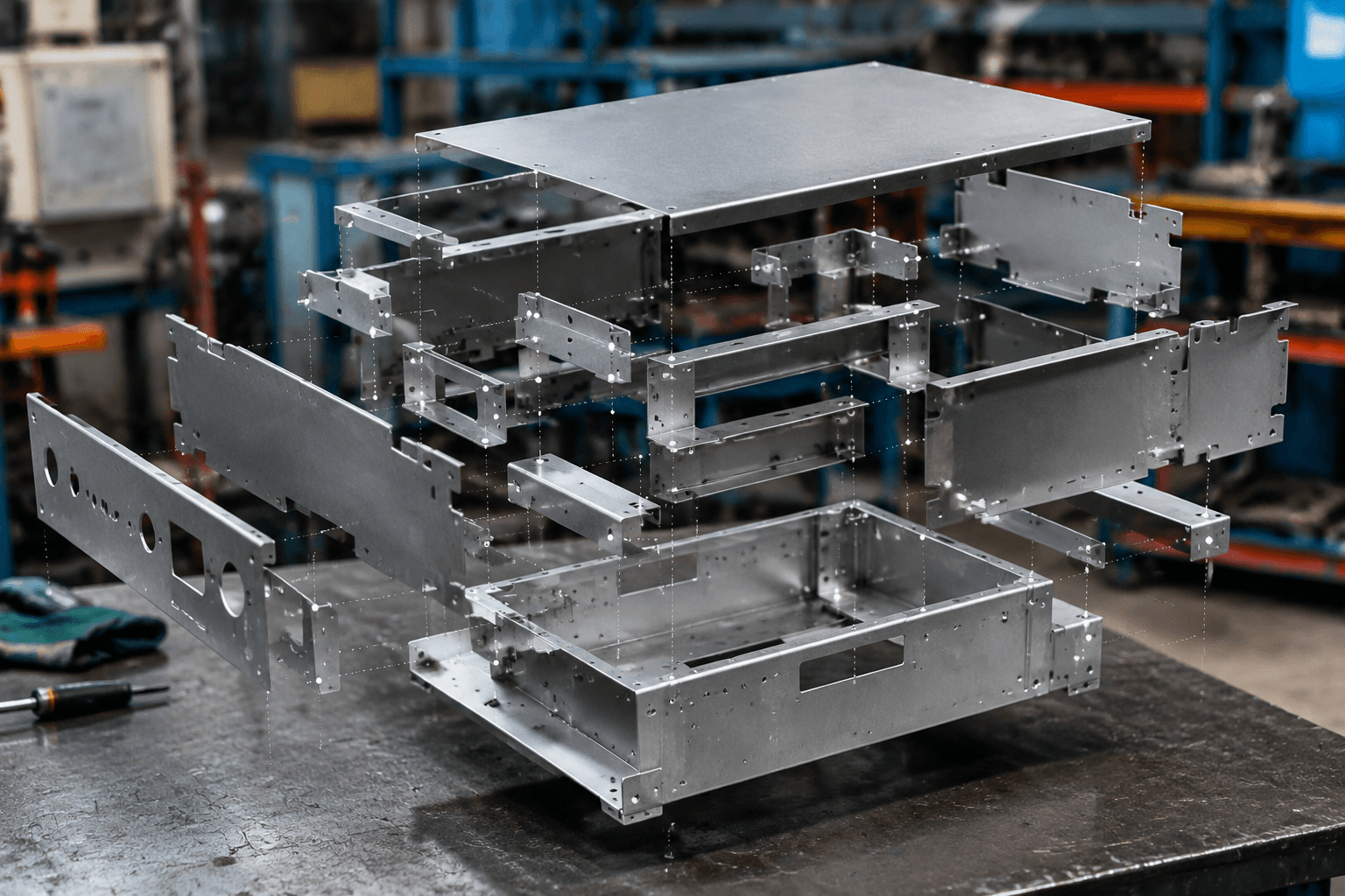
Complex assemblies are multi-part metal products whose components or subassemblies must locate, join, and function together through controlled interfaces. For an OEM or ODM buyer, the review therefore covers more than individual part prices: formed panels, brackets, frames, hardware, and customer-installed items must fit, remain accessible, and move through the required inspection stages.
Quick answer: A single laser-cut panel is a component. A welded frame is an assembly, but not necessarily a complex one. A complex assembly contains parts or subassemblies whose interfaces and build sequence must be managed together so the finished product can meet its fit and functional requirements.
For example, consider a hypothetical enclosure with a formed outer shell, internal brackets, a structural frame, removable panels, fasteners, and customer-installed equipment. Its complexity depends on whether those elements align, remain accessible, and can be inspected in the required sequence. Another product may contain more parts yet be easier to build because its interfaces are independent and loosely constrained.
What Is a Complex Assembly?
There is no universal part-count threshold or formal classification that separates a simple assembly from a complex one. In custom metal manufacturing, the term generally describes a final product or major module in which several parts or subassemblies must be located, joined, checked, and sometimes installed in a defined order. For an OEM buyer, this distinction matters because a supplier may quote the components separately while the assembly-level interfaces still require review before scope and responsibility are agreed.
| Product level | Meaning | Primary control focus |
|---|---|---|
| Single sheet metal component | One fabricated item, such as a panel, bracket, or formed cover. | Material, part geometry, holes, bends, and specified finish. |
| Simple welded assembly | A limited group of parts permanently joined into one unit. | Joint location, weld access, squareness, distortion, and basic fit. |
| Subassembly | A defined module intended for installation into a larger product. | Datums, external interfaces, inspection points, and handoff condition. |
| Complex final assembly | Multiple components or subassemblies coordinated as a complete product. | Interface fit, tolerance stack-up, joining sequence, access, revisions, and final verification. |
A frame, rack, cabinet, or enclosure does not become complex merely because it is welded or contains several pieces. Complexity increases when panels, brackets, hardware, and other modules must align with the structure while remaining accessible for installation, inspection, service, or customer-side integration. Structural custom metal frames, for example, may be delivered as final products or as controlled subassemblies within a larger build.
Where Assembly Complexity Comes From
Part count alone is a poor guide to assembly difficulty. A single component can have demanding geometry, while a group of simpler parts can become difficult when one feature affects several interfaces. For buyers, this distinction helps direct design review toward the relationships that control fit and build sequence.
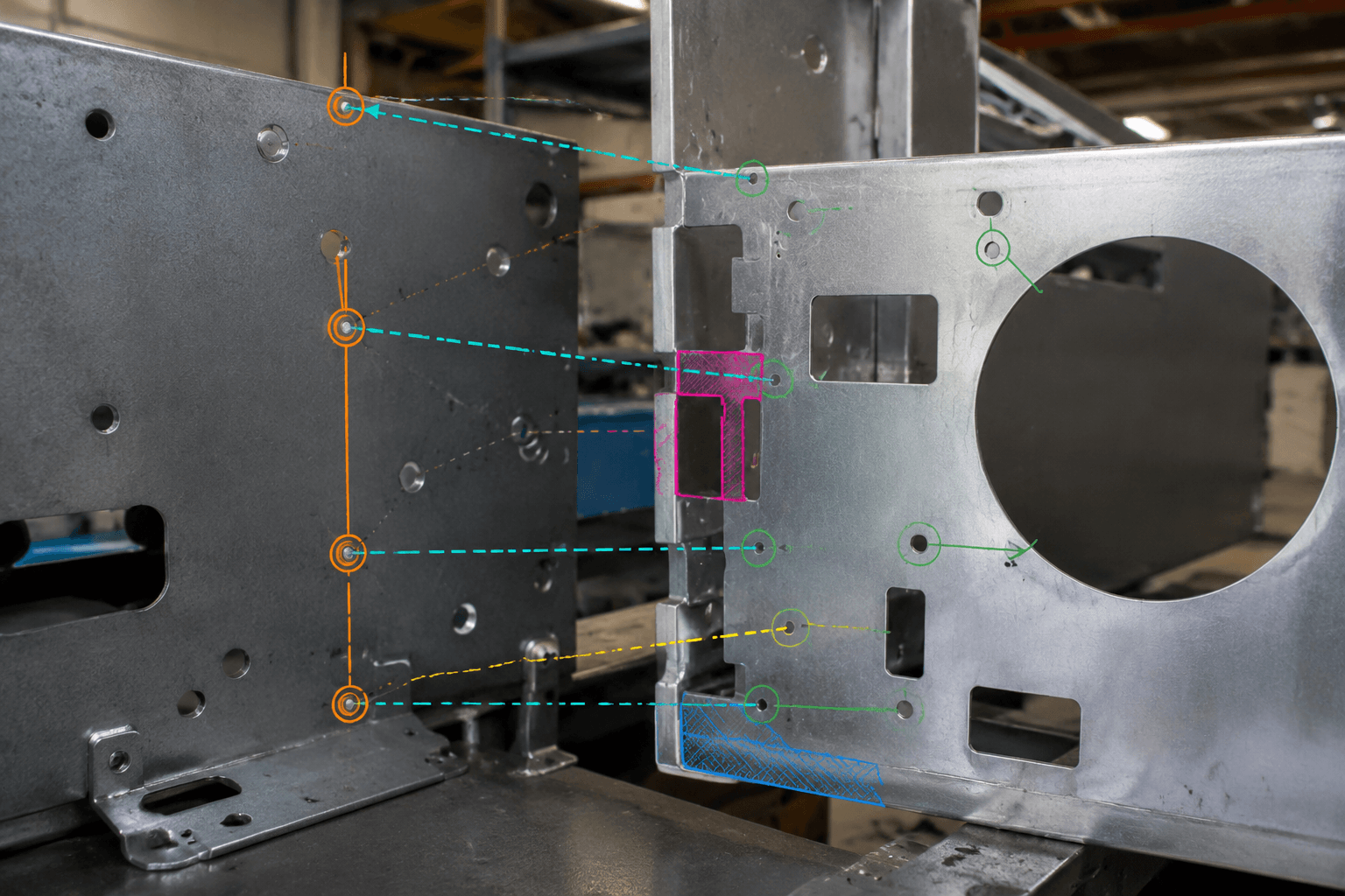
Interfaces and locating features: Mating surfaces, hole patterns, slots, flanges, brackets, and locating edges establish relationships between parts. A hole can be correct relative to its own part drawing but still fail to align if the mating component uses a different datum or a bend changes the hole’s final position.
Tolerance stack-up: Final fit may depend on the combined location of a base feature, bend, welded bracket, and mating hole pattern. The relevant dimensions should be traced from a functional datum to the final interface. Cosmetic or non-functional dimensions usually do not require the same attention as dimensions that control fit.
Joining and access: Welds, fasteners, inserts, and other specified hardware impose different access requirements. A joint may look feasible in CAD yet be difficult to reach with a welding tool, wrench, driver, inspection device, or hand. Access can also disappear after another panel or bracket has been installed.
Sequence and inspection: Assembly order determines when parts can be positioned, joined, measured, adjusted, or replaced. Inspection points therefore need to follow the build sequence rather than being left until the product is closed.
Revision control: A revision to one bracket or hole pattern can affect several mating items. The assembly model, component drawings, bill of materials, and inspection requirements must identify a consistent product revision.
Complex Assembly Review Matrix: Questions to Answer Before Production
| Complexity driver | Review question | Potential manufacturing implication | Evidence to provide |
|---|---|---|---|
| Interfaces | Which surfaces, edges, and holes locate the product? | The datum and fixture approach may need clarification. | 3D CAD, interface drawings, and marked critical features. |
| Tolerance chains | Which dimensions accumulate to determine fit? | Fit-related dimensions may require different controls from cosmetic features. | 2D drawings with the relevant chain identified. |
| Joining | Which joints are permanent, and which are removable? | Joint selection affects access, distortion, service, and assembly order. | Weld symbols, hardware list, and joining notes. |
| Access | Can tools and hands reach each joining and installation point? | An opening, flange, or installation order may need revision. | Assembly model and an access review. |
| Sequence | What must be installed before an area is closed? | Incorrect sequencing can block installation or inspection. | Assembly sequence and intended delivery state. |
| Revision control | Do CAD files, drawings, and the BOM show the same revision? | Mixed documents can create interface mismatches. | A current, controlled document package. |
| Inspection | What is checked at component, subassembly, and final levels? | Inspection gates should correspond to accessible build stages. | Defined inspection points and acceptance requirements. |
From Individual Parts to an Integrated Product
The manufacturing route should follow the product’s geometry, material, joint requirements, quantity, and agreed delivery state. Not every complex assembly uses every operation below, so process selection should follow the design rather than a manufacturer’s capability list.
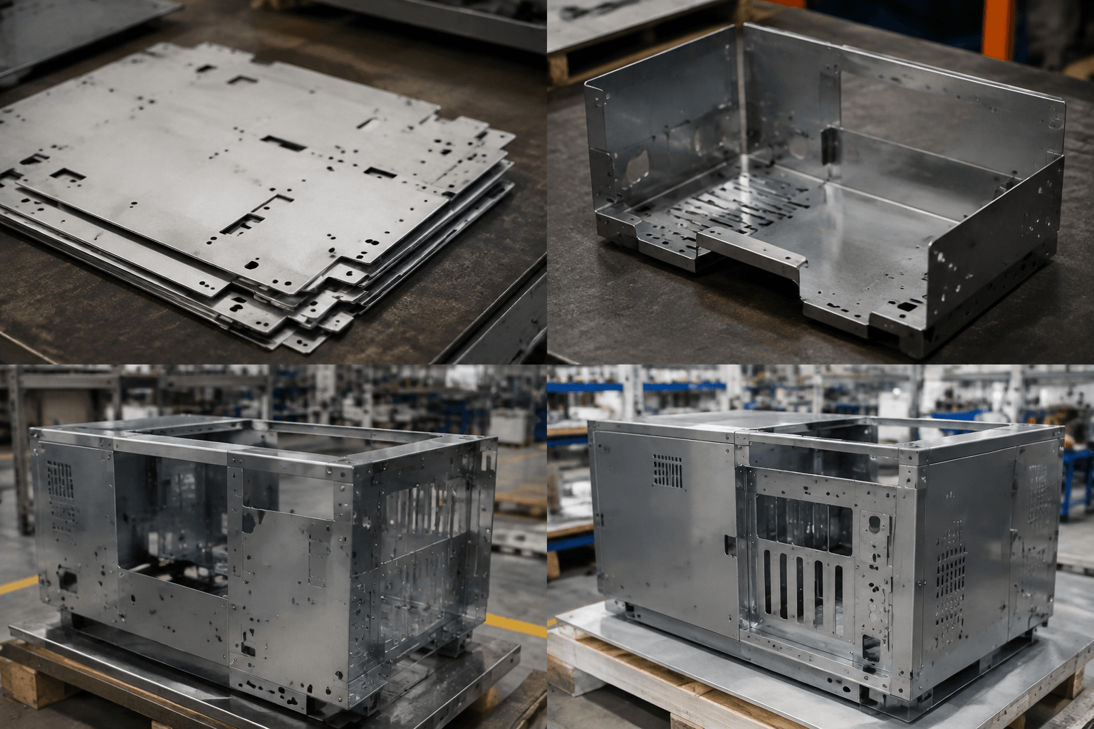
- Create blanks and specified features. Laser cutting or CNC punching may produce outside profiles, holes, slots, and related features. A project may use one method, a combination, or another agreed blank-making route depending on the parts.
- Form the components. Bending creates flanges, panels, brackets, channels, and other formed shapes. Bend direction, relief, flange relationships, and forming order affect where mating features end up in the finished part.
- Make permanent joints where specified. Welding can combine parts into a frame, cabinet, rack, or structural subassembly. It is a joining process, not a synonym for final assembly. Joint access, sequence, and the potential effect on surrounding interfaces need review before other parts close the area.
- Integrate parts and hardware. Assembly brings together fabricated components, welded subassemblies, removable panels, brackets, inserts, fasteners, and other agreed items. Supplier-performed final assembly is a defined project scope, not an automatic part of sheet metal fabrication.
Some products consist of cut and bent parts connected entirely with removable hardware. Others are supplied as welded subassemblies for installation by the customer. A finish requirement enters the assembly review only when it affects mating surfaces, masking, handling, electrical contact areas, or installation order. Part-level requirements can be reviewed through custom sheet metal fabrication built to your drawings.
A Design Review Sequence for Fit and Repeatability
Fit and repeatability are decided at the interfaces between parts, not only by the accuracy of each individual component. A design review should therefore connect the CAD model, drawings, BOM, revision status, and inspection plan before production begins.
- Confirm the product hierarchy. Review the 3D CAD assembly, 2D assembly drawing, component drawings, BOM, and revision status together. Identify fabricated parts, purchased hardware, customer-supplied items, and anything outside the manufacturer’s scope.
- Choose functional datums. Establish the base, centerline, locating surface, or other feature from which critical interfaces are controlled. An incidental cosmetic edge should not become the primary reference when a more stable functional feature is available.
- Trace each critical tolerance chain. Follow the controlling dimensions from the datum through cut features, bends, welded brackets, hardware, and mating panels. Distinguish fit and functional dimensions from dimensions that primarily control appearance.
- Review features in their formed condition. Check hole-pattern alignment, bend relief, flange relationships, possible collisions, weld access, fastener access, tool clearance, and handling space. Flat-pattern alignment alone does not establish assembled fit.
- Set the assembly order. Decide which parts are formed and checked first, which joints are completed next, and which openings must remain accessible. A removable panel or selected hardware may need to wait until a welded core has been inspected.
- Define verification points. State what will be inspected on individual components, after permanent joining, and after final integration. A prototype or sample review can be used to examine fit, access, joining, and assembly order before batch production.
Preparing an early project review? Send the current 3D CAD assembly model, 2D assembly and component drawings, BOM, revision status, material, joining, hardware, and applicable finish requirements, along with critical interfaces and inspection points. Adding target quantity and prototype needs clarifies what the manufacturer must review and what remains outside the requested scope. A sample review can then focus on fit, access, joining, and assembly order before batch production.
Evidence of Manufacturer Readiness
A machine list alone does not show whether a manufacturer can control an assembly. OEM buyers should look for evidence that the complete product definition and its handoff condition have been reviewed before production is released.
- Complete-product interpretation: Can the manufacturer read the assembly drawing and BOM together, identify the subassemblies, and state what will be delivered?
- Documented technical questions: Are unclear datums, missing hardware details, conflicting revisions, inaccessible joints, and high-risk interfaces recorded before production?
- Prototype or sample review: Is there a proposed method for checking fit, joining access, assembly order, removable parts, and customer installation steps?
- Inspection by build stage: Are component checks, welded or mechanically joined subassembly checks, and final assembly checks assigned to suitable points? These expectations can be compared with the manufacturer’s published quality control information.
- Defined handoff: Are the delivery state, labels, packaging assumptions, hardware status, surface protection, and remaining customer-side work clear?
Scope exclusions matter as much as inclusions. Fasteners or other purchased items may be supplied when agreed, but should not be assumed. Electrical, electronic, hydraulic, or software integration also remains outside the metal assembly scope unless responsibility is specifically assigned.
Complete Assembly or Controlled Subassemblies?
The delivery decision affects final-fit responsibility, shipping size, handling risk, inspection, service access, and the customer’s production-line sequence. It should be agreed from the drawing package, BOM, assembly order, and installation plan.
| Delivery state | Often practical when | Points to define |
|---|---|---|
| Complete assembly | The customer wants one integrated unit and can receive, handle, and install it in that condition. | Final-fit responsibility, hardware completeness, inspection, packaging protection, and service access. |
| Controlled subassemblies | The product is difficult to ship as one unit or must enter the customer’s production process in stages. | Handoff interfaces, protected mating features, labels, inspection status, and responsibility for final fit. |
A welded frame may be delivered as a structural subassembly while removable panels, brackets, or selected hardware are installed later. An enclosure may instead be delivered as a complete metal unit when that condition suits the customer’s installation process. Inspection and packaging should correspond to the agreed handoff points. Relevant enclosure configurations can be explored through custom sheet metal enclosures.
Planning a complex assembly RFQ? Yishang supports B2B OEM and ODM custom manufacturing projects, has more than 26 years of custom metal manufacturing experience, and exports to more than 50 countries. Send the 3D CAD files, 2D assembly and component drawings, current BOM and revision status, material and joining requirements, applicable hardware and finish requirements, critical interfaces, fit requirements, inspection points, target quantity, prototype needs, and preferred delivery state. Yishang can then review the fabrication, welding, assembly, documentation, and handoff route the product actually requires.
Frequently Asked Questions
These questions address the distinctions OEM buyers most often need to settle before requesting a quotation for a custom metal assembly, subassembly, or prototype.
What qualifies as a complex assembly in sheet metal manufacturing?
There is no universal part-count threshold. Complexity arises when multiple components or subassemblies must be coordinated through critical interfaces, tolerance chains, joining methods, access constraints, assembly stages, revision controls, and inspection requirements.
Is a welded assembly automatically a complex assembly?
No. A welded frame with accessible joints and few mating requirements may be straightforward. Welding is one joining method; assembly complexity depends on how the structure interacts with other parts, hardware, subassemblies, and inspection points.
Should a complex metal assembly be delivered fully assembled or as subassemblies?
A complete assembly may suit customers that want one integrated unit and can handle it as delivered. Controlled subassemblies may be more practical when shipping, service access, production-line sequencing, or customer-side integration requires staged handoffs. Responsibility for fit should be defined at each handoff.
What files and information should an OEM provide for a complex assembly review?
Provide the 3D CAD assembly, 2D assembly and component drawings, current BOM and revision status, material and joining requirements, applicable hardware and finish requirements, critical interfaces, fit requirements, inspection points, target quantity, prototype needs, and preferred delivery state.