
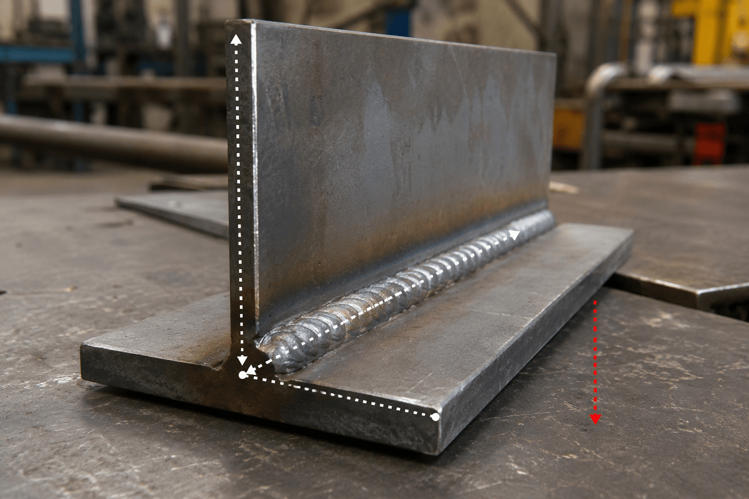
A 2F weld is a fillet weld made in the horizontal welding position. The number 2 identifies the horizontal position, while F identifies a fillet weld joining two members, typically a horizontal surface and a vertical surface.
What Is a 2F Weld?
In a typical 2F joint, one component presents a horizontal surface and the other rises vertically from it. The fillet weld is deposited in the inside corner, often on the upper side of the horizontal member. The weld axis, meaning the line running along the length of the weld, is horizontal.
The position label describes how the joint is oriented while it is being welded; it does not name the welding process. MIG, TIG, stick, flux-cored, or another process may be selected only when suitable for the material, joint, and applicable procedure. A 2F label therefore tells a fabricator about joint position and weld type, not the complete production method.
2F vs 1F vs 2G: How the Labels Differ
The quickest way to classify the joint is to identify the weld type first. The letter F means fillet weld, where the weld joins surfaces that meet at an angle. The letter G means groove weld, where the weld is made in a groove between prepared edges.
| Position | Weld type | Typical orientation | Identifying feature |
|---|---|---|---|
| 1F | Fillet | Flat position | The joint is arranged so the fillet can be deposited from above in a flatter orientation. |
| 2F | Fillet | Horizontal position | The fillet weld axis is horizontal, commonly joining a horizontal member to a vertical member. |
| 2G | Groove | Horizontal position | The weld axis is horizontal, but the weld is deposited in a groove rather than an outside-corner fillet. |
Thus, 2F and 2G share the number because both use the horizontal position, but they do not describe the same joint. The letter changes the meaning. Similarly, 1F and 2F are both fillet-weld positions, but 1F is flat while 2F is horizontal. The wider F-position naming system also includes labels such as 3F and 4F; those are useful context, but they do not change how the 2F label is decoded.
Why Horizontal Fillet Welding Requires Puddle Control
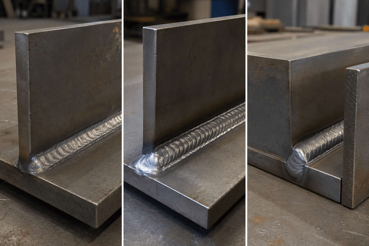
In 2F welding, gravity acts on the molten weld pool while the joint corner supports it unevenly. If the pool becomes too fluid or too large, molten metal can sag toward the lower side of the joint instead of remaining centered in the fillet. This may produce an uneven profile, overlap, insufficient fusion at one side, or excess buildup, depending on the process and joint conditions.
Good setup begins with the joint itself. Members should be held in the intended orientation, with fit-up and access consistent with the drawing and applicable welding procedure. The operator then needs to manage puddle size and fluidity rather than allowing the pool to outrun the joint. Controlled travel, a consistent progression, and avoiding unnecessary pauses are general considerations, but the exact technique depends on the welding process, material, thickness, joint design, and procedure.
For this reason, a 2F label should not be treated as a universal recipe. It does not establish a particular current, voltage, travel speed, filler, shielding arrangement, or electrode choice. Those details must come from the project specification and the procedure applicable to the selected process. The key practical point is that horizontal fillet welding gives gravity a greater opportunity to pull a fluid pool toward the lower side, so stable control is important.
Understanding the 2F Angle and Joint Orientation
Two angle terms are often confused. The work angle describes the position of the electrode, torch, or welding tool across the joint. In a conventional fillet-joint illustration, a 45-degree work-angle concept is commonly shown because it bisects the corner formed by the two members. That illustration helps explain how the weld can reach both joint faces.
The travel angle is different. It describes the tool’s forward or backward inclination in relation to the direction of travel along the weld axis. It is not simply another name for the work angle. Neither angle should be assumed to be 45 degrees for every 2F weld. Joint clearance, member thickness, process, consumable, access, and the applicable procedure can all change the required setup and manipulation.
Orientation is equally important. A fabricator may rotate a workpiece so a joint that was difficult to access becomes a flatter or more controllable weld. Once the assembly is repositioned, the actual welding position may no longer be 2F. Conversely, a large frame or enclosure may have to remain in a particular orientation because of size, fixtures, attached components, or access limitations. The classification should describe the joint as welded, not merely the way it appears in a three-dimensional assembly model.
How to Identify and Communicate a 2F Weld on a Project
When a drawing or assembly view is ambiguous, use four checks before calling the joint 2F. This avoids confusing a horizontal fillet with a flat fillet or a horizontal groove weld.
| Question | What to inspect | What it tells you |
|---|---|---|
| 1. What is the joint type? | Look for two surfaces meeting at an angle or for prepared edges forming a groove. | An outside-corner or T-joint fillet points toward F; a prepared groove points toward G. |
| 2. Which way does the weld axis run? | Follow the weld along its length, rather than judging only the assembly’s front view. | A horizontal weld axis supports a 2-position classification. |
| 3. How are the members oriented while welding? | Identify the horizontal member, vertical member, and location of the fillet in the corner. | A typical horizontal-to-vertical fillet arrangement supports 2F. |
| 4. Can the workpiece be repositioned? | Check fixture access, assembly size, attached parts, and the required weld sequence. | Rotation may change the actual welding position and should be stated clearly. |
Use the weld symbol, section views, assembly orientation, and any applicable welding procedure together. A symbol may identify the weld type and size, but a separate view or note may be needed to show which side is welded and how the assembly is held. If the position is not obvious, send a marked-up sketch or photograph with arrows showing gravity direction, the weld axis, and the orientation during welding.
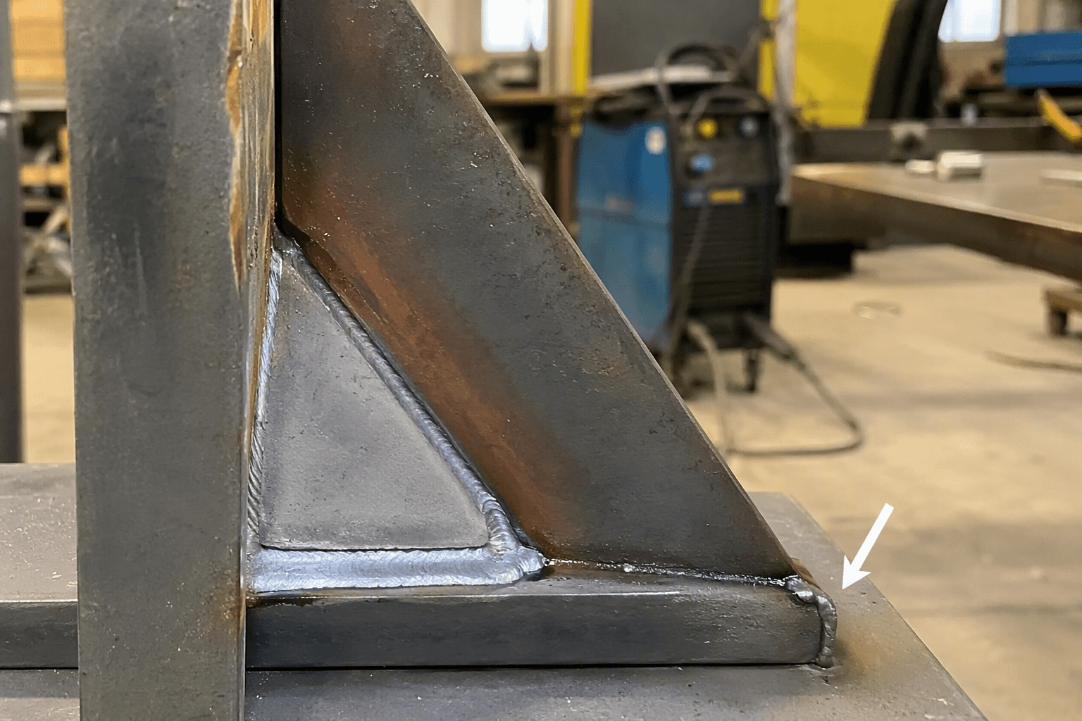
This clarification is especially useful for welded metal brackets built to drawings, frame assemblies, and sheet metal enclosures with specified welded joints. For larger structures, a drawing review can also confirm whether a custom metal frame assembly can be rotated during fabrication or must be welded in its installed orientation.
Frequently Asked Questions
What is the difference between a 1F and a 2F weld?
Both are fillet welds, but 1F is made in the flat position while 2F is made in the horizontal position. The joint may look similar in a drawing, so the orientation during welding and the direction of the weld axis must be checked.
What is the difference between a 2F and a 2G weld?
The number 2 indicates the horizontal position in both labels. F means fillet weld, typically at an inside corner, while G means groove weld between prepared or aligned edges.
Is a 45-degree torch or electrode angle always required for 2F welding?
No. A 45-degree work-angle illustration is a common way to show the tool bisecting a fillet-joint corner, but it is not a universal torch, electrode, or travel angle. The joint, process, access, and applicable procedure control the actual setup.
Why can the weld puddle sag in the 2F position?
Gravity pulls on molten metal, and a fluid or oversized puddle can move toward the lower side of the horizontal joint. Puddle size, travel control, fit-up, material, process, and procedure all affect how that tendency is managed.
Need to confirm a drawing before production? Share the relevant drawing or weld symbol, a photo or sketch showing assembly orientation, and the joint type, material, thickness, and any specified welding procedure. Yishang supports OEM and ODM custom manufacturing for B2B projects and can help clarify whether the joint is correctly classified as 2F before fabrication.