
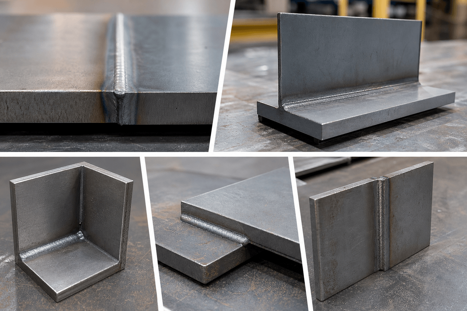
The 5 basic joints in welding are butt, tee, corner, lap, and edge joints. They describe how two parts meet, while the welding process, weld profile, and inspection requirements determine how that joint is produced and assessed.
Quick answer: A butt joint joins parts in the same plane, a tee joint places one part perpendicular to another, a corner joint forms an L shape, a lap joint uses overlapping parts, and an edge joint joins adjacent parallel edges. The appropriate configuration depends on thickness, fit-up, loading, access, distortion risk, and inspection requirements.
These configurations appear in sheet metal assemblies, brackets, frames, enclosures, and larger fabricated structures. However, no joint type is automatically the strongest or most economical for every application. The complete part geometry and service conditions must guide the selection.
The Five Basic Welding Joints at a Glance
A joint configuration describes the orientation of the workpieces before welding. It is different from a welding process such as MIG, TIG, stick, or robotic welding. The same general joint configuration may be produced with different processes, depending on the material, thickness, production method, drawing requirements, and qualified procedure.
| Joint | Part orientation | Common high-level weld association | Primary design consideration |
|---|---|---|---|
| Butt | Parts meet end-to-end or edge-to-edge in the same plane | Groove weld, sometimes with edge preparation | Alignment, root fit-up, and access to one or both sides |
| Tee | One part meets another at approximately 90 degrees | Often a fillet weld; other details may be specified | Load direction, intersection access, and local stress concentration |
| Corner | Parts meet at an angle to form an L shape | Fillet or groove weld depending on the joint detail | Open or closed corner geometry and distortion control |
| Lap | One part overlaps another | Fillet, plug, slot, or other specified weld forms | Overlap, eccentric loading, thickness differences, and trapped gaps |
| Edge | Adjacent parallel edges are brought together | Edge or fillet-type weld detail depending on geometry | Limited load path, edge preparation, and inspection access |
The table is a starting point rather than a ranking. A drawing should define the required weld detail when the joint affects structural performance, sealing, appearance, or inspection.
Butt and Tee Joints: Coplanar Versus Perpendicular Parts
Butt joints
In a butt joint, two workpieces meet along their edges in the same plane. The parts may be aligned end-to-end, or two sheet edges may meet along a seam. The finished surface can be relatively flush when the joint is prepared and welded appropriately, which is useful where a continuous panel surface or a controlled profile is needed.
Butt joint section view

[ plate ] | [ plate ]
          ^
joint lineFit-up is central to a butt joint. Uneven gaps, mismatch, poor alignment, or insufficient access can affect the weld detail and the finished geometry. Thicker material may require a specified edge preparation, while thinner sheet may use a simpler edge condition. The correct preparation depends on the material, thickness, joint design, welding process, and project requirements; it should not be selected from a general rule alone.
Access also matters. If only one side is reachable, the drawing and procedure must account for that limitation. Two-sided access may allow a different preparation or inspection approach, but it can also introduce additional setup and distortion considerations. In a frame or enclosure, a butt seam may be easy to see from the outside but difficult to inspect or finish from the inside.
Butt joints are often considered where parts must transfer load along a relatively direct path or where a continuous surface is important. That does not make them automatically suitable for a highly loaded application. The engineer must still evaluate stress, thickness transitions, weld access, and the required inspection method.
Tee joints
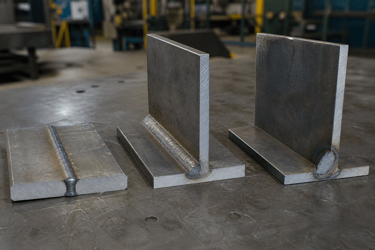
A tee joint places one workpiece approximately perpendicular to another, creating a T-shaped section. The upright part may be a stiffener, divider, mounting member, or bracket connected to a base plate.
Tee joint section view

       | upright
       |
=======|======= baseTee joints frequently use fillet welds along one or both sides of the upright member, although the final weld detail depends on the design. The intersection concentrates load around the weld and the connected base material, so load direction is important. A force parallel to the base does not affect the joint in exactly the same way as a force pulling the upright away from it.
Alignment and access deserve attention during fit-up. The upright must be positioned accurately, and weld access may be restricted where the member is close to another wall or component. Welding one side only may be practical for a light assembly, while a two-sided detail may be required by the design. Welding sequence and restraint can also influence angular distortion, which may cause a frame or bracket to move out of square.
For custom metal brackets or similar parts, the joint geometry should be reviewed together with fastener holes and assembly clearances. A useful reference is custom metal brackets built to your drawings, where perpendicular members and access around the intersection may affect manufacturability.
Corner, Lap, and Edge Joints: Angled, Overlapping, and Adjacent Edges
Corner joints
A corner joint connects two parts at an angle, commonly forming an L-shaped section. The corner may be open, with the edges meeting at the outside of the angle, or closed, with the parts arranged to create a more enclosed corner.
Corner joint section view

[ plate ]
     |
     | plate
     |
+Corner geometry appears in frames, boxes, cabinets, ducting, and enclosures. A fillet or groove-type detail may be used depending on the corner shape, access, appearance, and load path. Closed corners can be harder to reach and inspect internally. Open corners may be easier to weld but can require attention to visible weld profile, edge preparation, and distortion.
Thin panels are particularly sensitive to heat input and restraint because local distortion can change the squareness of the assembly. Fit-up should therefore control the angle and the size of any corner gap before welding. For enclosure work, seam location may also affect finishing, sealing, internal clearance, and the appearance of the final product. See the related example of custom sheet metal enclosures for the type of panel and seam geometry that may require this review.
Lap joints
A lap joint uses overlapping parts rather than placing their edges in the same plane. One sheet extends over another, and the weld is made along the overlap or through a prepared opening, depending on the design.
Lap joint section view

[ upper plate      ]
          [ lower plate          ]
overlapLap joints can accommodate parts with different thicknesses and may be useful when edge-to-edge alignment is difficult. Their practical behavior depends on the overlap length, weld location, thickness transition, and direction of applied force. Because the force may not pass through the same plane as the connected material, eccentric loading can introduce additional bending or local stress.
Fit-up should prevent unintended gaps, contamination, or trapped moisture where the design is sensitive to corrosion or sealing. Overlap can also make both sides of the interface less accessible for inspection and finishing. Where the joint is used in a thin sheet assembly, the designer should consider whether the overlap adds unnecessary material, creates a visible step, or interferes with a mating component.
Edge joints
An edge joint places adjacent parallel edges together, generally with the parts lying side-by-side or in closely aligned parallel planes. The weld fuses the edges rather than joining two broad faces through a substantial overlap.
Edge joint section view

[ plate ] [ plate ]
   edge   edge
joined areaEdge joints can suit certain light-duty panels, covers, flanges, or folded sheet metal features where the geometry naturally brings edges together. They have a limited load path compared with configurations designed to transfer substantial forces through a broader or more direct connection. For that reason, an edge joint may be unsuitable for a highly stressed or heavily loaded application unless the complete design and engineering review support it.
Edge preparation, edge alignment, and access are important because there may be little material available around the weld. Distortion can change the panel position or create a visible waviness along the edge. Inspection may also be limited, particularly when the joint is narrow, enclosed, or finished after welding.
Choosing a Joint Configuration for Real Project Conditions
Joint selection should begin with the geometry and load path, then move through fabrication and inspection constraints. The following comparison highlights the questions that should be resolved before a weld detail is finalized.
| Project factor | Questions to ask | Why it changes the decision |
|---|---|---|
| Thickness | Are the parts similar or different in thickness? Is edge preparation practical? | Thickness changes fit-up, heat response, edge preparation, and the available weld area. |
| Loading | Is the joint carrying tension, shear, bending, vibration, or a combination? | Force direction affects stress concentration and whether an overlap or perpendicular intersection creates eccentric loading. |
| Alignment | Must the parts remain coplanar, square, angled, or flush? | The joint may need to preserve a surface, angle, frame dimension, or assembly clearance. |
| Access | Can the welder reach one side or both sides? Is the interior accessible? | One-sided access can limit preparation, weld placement, sequence, and inspection options. |
| Distortion | Are the parts thin, long, restrained, or sensitive to angular movement? | Heat and restraint can change flatness, squareness, corner angle, or final fit. |
| Inspection | Can the weld and surrounding material be visually or otherwise inspected as required? | Hidden overlap, enclosed corners, and narrow edges can make defects or incomplete access harder to evaluate. |
For a welded frame, for example, the chosen configuration must preserve alignment at intersections while leaving enough access for welding and checking. Custom metal frames built square and ready to assemble illustrate why joint design cannot be separated from the complete assembly geometry.
The weld form is a separate decision. Fillet welds, groove welds, plug welds, and other profiles describe how material is deposited or connected at the joint. MIG, TIG, stick, and other welding processes describe how the weld is made. The joint configuration does not by itself determine the process, filler material, parameters, or inspection method.
What to Verify Before Specifying a Welded Joint
Before releasing a drawing for manufacture, verify the following sequence:
- Identify the joint orientation: coplanar, perpendicular, angled, overlapping, or edge-to-edge.
- Record the material, thickness, and any differences between connected parts.
- Show the expected load direction and service conditions, including movement or vibration where relevant.
- Confirm whether welding is possible from one side or both sides and whether the joint can be inspected after assembly.
- Define the required weld detail, appearance, access, and any drawing or engineering review requirements.
- Check fit-up, assembly clearances, distortion control, and access for welding and inspection.
A section view is often more useful than a general elevation because it makes the relationship between the parts and the weld location clear. When the joint affects structural performance, sealing, safety, or a critical assembly interface, the final detail should be reviewed and approved by the responsible engineer.
For an OEM or ODM project, Yishang can review the joint configuration in the context of the actual part or assembly. Share the relevant drawing, material and thickness information, expected loading or service conditions, weld locations, access constraints, and inspection expectations so the manufacturing discussion is based on the real geometry.
Frequently Asked Questions
What are the five basic types of welding joints?
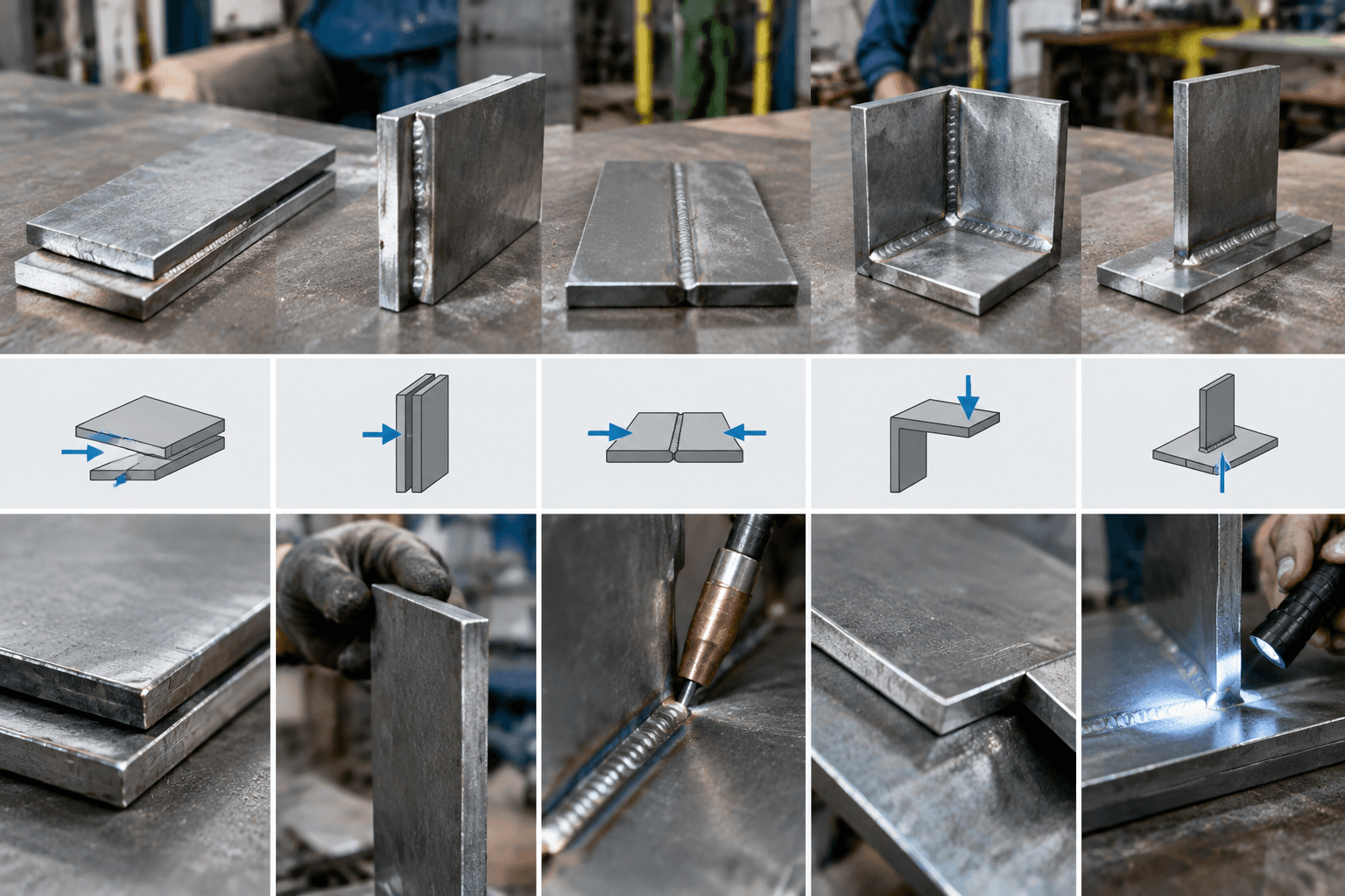
The five basic joint configurations are butt, tee, corner, lap, and edge. They describe how the parts are oriented and meet; they do not fully specify the weld profile or welding process.
What is the difference between a butt joint and a lap joint?
A butt joint places parts edge-to-edge in the same plane. A lap joint overlaps one part over another, which can simplify some fit-ups but may introduce eccentric loading, a thickness step, or more limited inspection access.
When might an edge joint be unsuitable for a highly stressed application?
An edge joint may provide a limited load path and limited material around the weld. If the assembly carries substantial tension, shear, bending, or vibration, another configuration may provide a more appropriate force path, subject to engineering review.
Does the joint type determine whether MIG, TIG, or another welding process must be used?
No. Joint configuration and welding process are separate decisions. Material, thickness, geometry, production requirements, access, drawing specifications, and qualified procedures influence process selection.