
Bending of manufactured parts is the controlled deformation of a sheet metal blank into angles, flanges, channels, or other three-dimensional geometry. For an OEM developing a bracket, enclosure, cabinet, frame, or folded panel, the key question is not simply whether the sheet can be bent. The design must also produce the required shape, fit, hole alignment, surface condition, and inspection results.
The blank may be cut or punched before it reaches the press brake, and the finished part may still require joining, machining, inspection, or finishing. A drawing review can identify important questions, but practical feasibility depends on the specified material, thickness, geometry, quantity, tooling, surface condition, and inspection requirements.
What bending means in custom manufactured parts
When a buyer sends a flat pattern or 3D model for a custom bracket or enclosure panel, bending is the forming stage that turns that blank into the intended functional geometry. Force is applied along a defined bend line, pushing the sheet beyond its elastic range so it retains a new angle after the tooling is released. Unlike cutting or punching, the operation normally changes the shape without removing material to create the main flanges or walls.
A single blank can become an L-shaped mounting bracket, a U-shaped channel, a folded cover, or a multi-sided enclosure panel. Cabinets, frames, equipment guards, mounting rails, and support brackets often use several bends to add stiffness and create interfaces for fasteners or mating parts. One formed sheet may replace several flat pieces, although joining, machining, inspection, or finishing can still be necessary elsewhere in the assembly.
The blank may first be prepared through Custom Sheet Metal Fabrication Built to Your Drawings, using a suitable cutting or punching route. Bending then gives the blank its three-dimensional form; it does not replace blank preparation or every downstream operation.
From a flat blank to a formed part
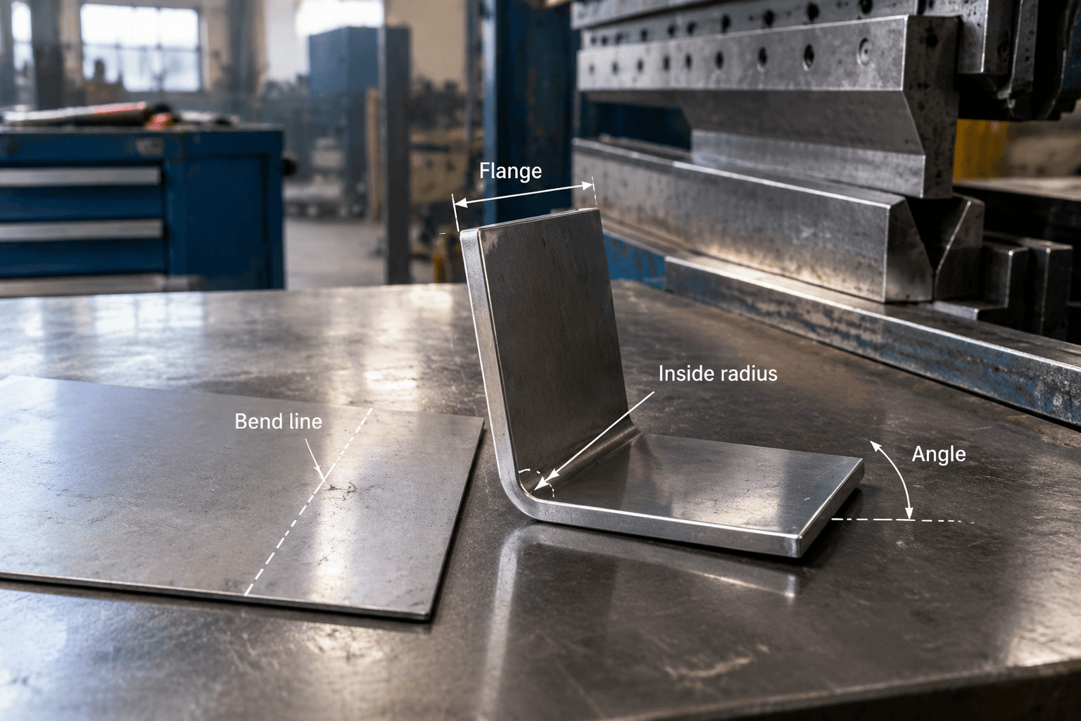
In a typical press-brake operation, the blank is positioned over a die and pressed by a punch. The tooling forces the sheet around the die opening, establishing the bend line, angle, and inside radius. Air bending, bottoming, and other approaches can be suitable in different situations, so the forming method must be considered with the material, thickness, geometry, tooling, and required repeatability.
Bend angle describes the relationship between the two formed legs, while the inside radius describes the curved transition on the inner surface. Because angle conventions can vary, the drawing should state whether it uses an included angle or another convention. It should also identify whether a radius is an inside or outside requirement.
A tight inside radius increases strain and may be unsuitable for a particular alloy, thickness, grain direction, surface condition, or tooling arrangement. A larger radius may improve formability but alter the part envelope, hole position, corner clearance, or assembly fit. The selected die opening and punch geometry also affect the practical result.
Multiple bends introduce another consideration: sequence. A flange formed early may obstruct the punch or die during a later operation, while the order of operations can affect part orientation, operator access, dimensional accumulation, and marks on cosmetic surfaces. A design that looks straightforward in a 3D model may still require a tooling and rotation review.
Springback is the tendency of the material to recover part of its elastic deformation after the forming force is released. The finished angle may therefore be more open than the angle under load, and the machine setup angle may differ from the released part. The process can compensate through overbending or another controlled adjustment, but the amount varies with material grade and condition, thickness, radius, tooling, and geometry.
For blank preparation, the formed geometry is developed into a flat pattern using bend allowance or a related calculation. This accounts for material behavior around the bend rather than simply adding visible flange lengths. There is no universal allowance value; the result depends on the forming method, tooling, material, thickness, and part configuration. The manufacturing flat pattern should be coordinated with, but not confused with, the dimensions that control the finished part.
Design details to review before releasing the part
Before releasing a bracket, enclosure, or folded panel, review the material, thickness, and bend geometry together rather than selecting a radius in isolation. Aluminum, stainless steel, mild steel, and other sheet materials can respond differently under the same tooling conditions. Even within one material family, strength, temper, rolling direction, surface condition, and thickness can change the forming response.
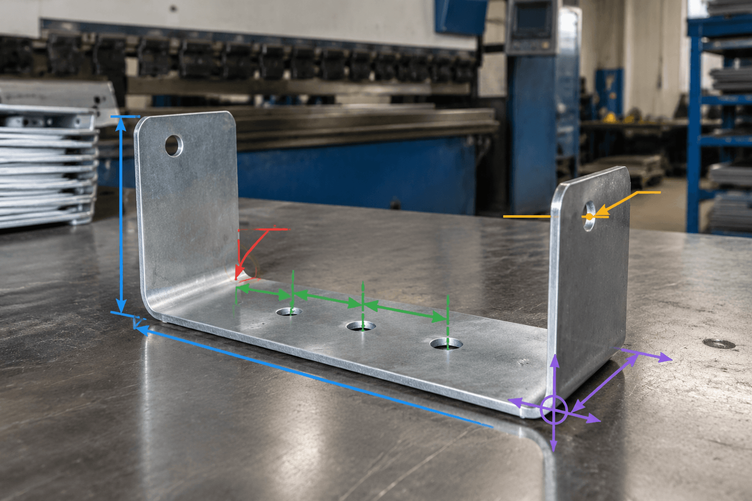
The inside radius should suit the selected material and thickness. A radius that is too tight may cause cracking, distortion, excessive tool marks, or an unacceptable change to the outside surface; a larger radius may improve formability while affecting the envelope or nearby features. Flange length must also provide sufficient contact for the selected tooling and perform its intended structural or assembly function. There is no single minimum radius or flange length for every press brake, material, thickness, and bend method.
Holes and slots close to a bend can elongate, distort, or shift as the surrounding material is strained. They may also interfere with the punch or die. Appropriate spacing depends on feature size, bend direction, radius, thickness, tooling, and positional tolerance, so a mounting hole that must align with a mating component should be reviewed against the actual bend sequence.
Bend relief near an outside corner or intersecting edge can help prevent tearing, bulging, or unwanted overlap. Its size should suit the material and geometry without weakening a load-bearing area or creating an unacceptable opening. Grain direction may also deserve explicit review when a tight bend or crack-sensitive material is involved, particularly on a blank with several bends.
Design priorities vary by application. A mounting bracket may depend on hole alignment, flange angle, and stiffness; an enclosure may require consistent corner appearance, cover clearance, and accurate fastener locations; and a cabinet frame may need several bends to remain square enough for panels and hardware to fit.
A compact DFM review matrix
| Feature | Potential manufacturing risk | Review question |
|---|---|---|
| Material and thickness | Different forming response, cracking risk, or springback | Is the specified grade and thickness compatible with the required angle and radius? |
| Inside radius | Excessive strain, marks, distortion, or an altered part envelope | Is the radius functional, and is it identified as inside or outside? |
| Flange length | Insufficient tooling contact or unstable forming | Can the selected punch and die form the flange without interference? |
| Hole or slot near a bend | Feature distortion, positional shift, or tool collision | Will the feature remain functional after forming and remain practical to inspect? |
| Corner and bend relief | Tearing, bulging, sharp edges, or reduced local strength | Does the relief protect the bend without compromising the assembly? |
| Multiple bends | Sequence interference and accumulated dimensional variation | Can the part be supported, rotated, and accessed through every operation? |
| Tight tolerances | Greater sensitivity to springback and a more demanding inspection plan | Which dimensions are critical to function, and which can use a broader tolerance? |
| Assembly interfaces | Misalignment with mating parts, hardware, or weldments | Are formed-condition dimensions and datums tied to the actual assembly function? |
Specify and inspect the formed condition
A 2D drawing or 3D model should define the shape and identify the features that matter after forming. For a bent part, the documentation should state the material grade, sheet thickness, units, bend angles, bend direction where ambiguity is possible, and required inside or outside radius. A model should not be the only source of a critical requirement if the bend convention could be interpreted differently by manufacturing or inspection personnel.
| Drawing or model item | What it should communicate | Why it matters |
|---|---|---|
| Material and thickness | Grade, temper or condition where relevant, thickness, and units | These variables affect forming behavior, springback, weight, and tool selection. |
| Formed geometry | Bend angles, bend direction, inside radius, overall dimensions, and clear views | They define the delivered part rather than only the cutting blank. |
| Functional datums | Datums connected to mounting holes, mating edges, or assembly planes | Inspection can reflect how the part functions in the product. |
| Feature requirements | Hole and slot sizes, locations, edge conditions, reliefs, and deburring expectations | Features near bends can be affected by forming and need deliberate control. |
| Tolerance priorities | Critical linear, angular, positional, and profile tolerances | Very tight tolerances everywhere can create unnecessary process and inspection difficulty. |
| Surface requirements | Cosmetic faces, allowable marks, visible edges, and any specified finish sequence | Tool contact and later finishing can affect appearance and fit. |
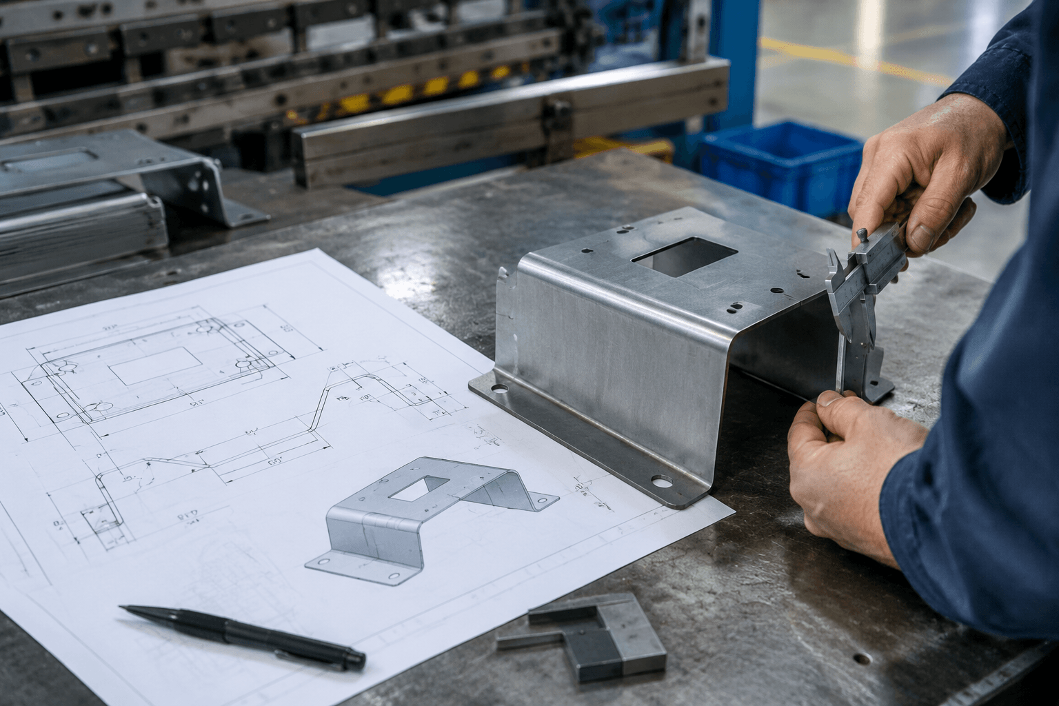
Inspection should distinguish the flat blank from the formed part. The blank can be checked for its cut profile, hole size, and pre-form features, while the completed part must be checked for angles, flange positions, radii, twist, overall dimensions, and assembly interfaces. A fixture, height measurement, angle measurement, or coordinate inspection may answer a different question, so the method should match the tolerance and geometry.
Dimensions that control installation or performance should generally be communicated in the formed condition. A motor bracket, for example, may need control of hole-to-datum position and flange angle, while a noncritical enclosure return may not require the same limits. The inspection plan should align with the manufacturing route and actual assembly function rather than being assumed from the drawing alone.
Where bending fits among manufacturing routes
When an OEM is choosing a route for a new metal component, bending has a specific role: it deforms a sheet blank along defined lines. Laser cutting or CNC punching may prepare the blank, welding may join separate bent components into a frame or cabinet, and machining may add a localized precision surface or feature. These operations can be combined on one product without being interchangeable.
| Route | Main action | Typical fit and limitation |
|---|---|---|
| Sheet metal bending | Deforms a blank along one or more bend lines | Useful for brackets, channels, enclosures, cabinets, frames, and folded panels. It is governed by bend access, radius, flange geometry, and springback. |
| Cutting or CNC punching | Removes material to create the blank profile and openings | Often precedes bending. It creates holes, slots, notches, and the perimeter but not the final flanges. |
| Machining | Removes material with localized cutting tools | Suitable for pockets, precision interfaces, and solid or thick components. It is not a substitute for forming broad sheet flanges. |
| Welding fabrication | Joins separate parts through a permanent joint | Useful when one blank cannot produce the geometry or when a frame needs joined members. Weld distortion and joint inspection then become relevant. |
| Stamping | Forms sheet with dedicated dies, often for repeatable production | May suit specialized high-volume work or integrated features, but tooling investment and geometry must justify the route. |
| Deep drawing | Pulls sheet into a deeper cavity or cup-like form | Better suited to deeper drawn shapes than ordinary press-brake flanges. It is not interchangeable with bending. |
| Roll forming | Passes sheet continuously through successive forming stations | Can suit long, consistent profiles in production quantities. It differs from making individual parts with discrete press-brake bends. |
A product may use more than one route. A metal enclosure, for example, may be cut, bent, joined, inspected, and finished as a complete assembly. A bracket may only need cutting and bending, while a frame may require several bent members and joining. The appropriate route depends on geometry, required depth, number and location of bends, production quantity, joining needs, surface expectations, and tolerance priorities.
For application examples, see Custom Metal Brackets Built to Your Drawings and Custom Sheet Metal Enclosures That Arrive Ready to Assemble. These examples show common uses for bent geometry, but a product category alone does not confirm that a particular design is ready for production.
Prepare an engineering review before release
For a prototype review or batch-production discussion, provide the 2D drawing or 3D model with the material and sheet thickness, required quantity or production stage, critical dimensions, bend angles, assembly interfaces, and surface or cosmetic requirements where applicable. Identify visible faces, holes that must align, and tolerances driven by function.
Yishang can review whether the proposed custom sheet metal route is practical for the stated design and identify questions about bend sequence, feature spacing, radius, tolerance priorities, and formed-part inspection. This supports OEM or ODM development without assuming that every design is production-ready.
Share the relevant drawing or model when you need an engineering and manufacturability review. The goal is to clarify the design intent and the requirements that control forming, inspection, assembly, and any specified finish.
Frequently Asked Questions
Is bending the same as folding or forming sheet metal?
In everyday manufacturing language, folding and bending may describe similar operations, and both can change a flat sheet into a new shape. Forming is the broader term and can include bending, stamping, deep drawing, roll forming, and other processes. Here, bending refers specifically to controlled press-brake-style deformation along defined bend lines.
Why can the final bend angle differ from the angle shown in the machine setup?
Material springs back after the punch is removed, so the released part may open slightly from the loaded position. The difference depends on material strength and condition, thickness, inside radius, tooling, and geometry. The process may compensate for springback, but the setup angle and finished inspection angle should not be assumed to be identical.
How close can a hole or slot be to a bend?
There is no single spacing rule for every sheet metal part. The appropriate distance depends on the material, thickness, hole or slot size, bend direction, inside radius, tooling, and required positional tolerance. A feature that is too close may distort or interfere with the tooling, so its location should be reviewed against the actual bend sequence.
Should a bent part be dimensioned in its formed condition or as a flat pattern?
Dimensions controlling the delivered part, fit, or function should normally be communicated in the formed condition. The flat pattern remains important for blank preparation and should be coordinated with the formed model or drawing, but it should not replace clear formed-part requirements. If both are supplied, identify which dimensions are manufacturing references and which are inspection requirements.