
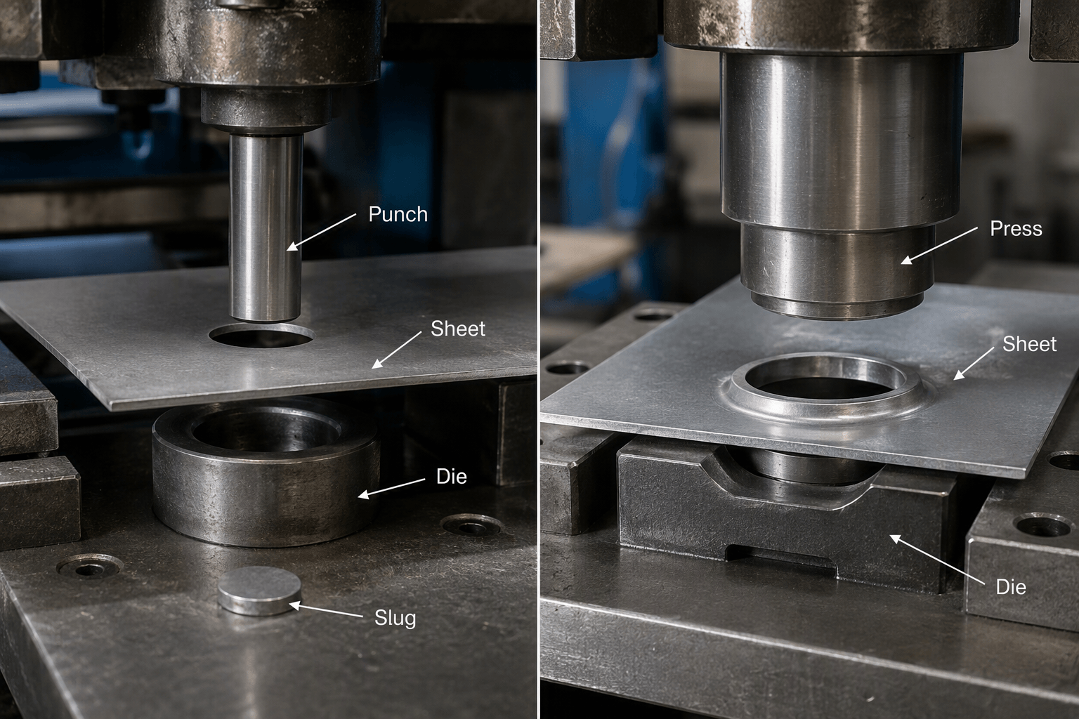
Pressing and punching are related, but they are not automatically the same sheet metal process. Punching is a specific punch-and-die shearing operation used to create holes, slots, and cutouts. Pressing is a broader or less precise term that may refer to stamping, forming, or other work performed with a press.
Terminology varies between suppliers and regions. Some use pressing or stamping as umbrella terms that include blanking and piercing; others use pressing to mean forming. For an OEM drawing, the required feature, finished geometry, quality criteria, and process sequence are more useful than the process label alone.
Pressing and punching: the terminology in practice
In sheet metal manufacturing, pressing describes force applied through a press and tooling to cut, bend, or plastically shape material. Punching describes one particular pressworking operation: shearing a section of sheet between a punch and a die until the material separates.
A pressed or stamped part may contain a formed flange, embossed stiffener, drawn recess, or shaped panel. A punched part may contain a round hole, rectangular slot, louver opening, or localized cutout. One part can include both categories, such as a panel with punched openings that is later bent into an enclosure.
The related terms also need to be used carefully. Piercing generally creates an opening, while blanking separates an outer profile and may leave the blank as the useful part. Both are shearing operations, even when they are carried out in a stamping tool. Forming changes the sheet’s shape without necessarily removing material, while drawing creates a deeper shape by moving material into a die cavity. A supplier should identify the actual operation, tooling arrangement, and sequence before a process label is treated as a quotation basis.
Press-based work covers more than one operation
Pressing is best understood as a press-based manufacturing family rather than one precisely defined operation. Depending on the die and the intended geometry, a press may perform blanking, piercing, bending, embossing, flanging, or drawing. The press supplies the force, but the die geometry and process sequence determine how that force changes the sheet.
For example, an embossed rib can add stiffness without removing material, a flange can create an assembly edge, and a drawn recess can produce depth from a flat blank. These features are not interchangeable. A drawn section requires assessment of material formability, corner radii, depth, potential wrinkles or cracks, and the forming sequence. An embossed feature presents different tooling, springback, and flatness considerations.
Tooling can be designed for one defined operation or arranged as several stages. A progressive arrangement may combine repeated actions across successive stations, while a single-operation tool may address one specific feature or part condition. Neither approach is universally better. The appropriate arrangement depends on geometry, material, quantity pattern, repeatability requirements, revision risk, and whether the tooling investment is acceptable.
Press-brake bending is normally specified as a separate sheet metal operation, even though it also applies force through tooling. It may follow punching as part of the same manufacturing route, but it should not automatically be described as pressing or stamping. For broader process context, see custom sheet metal fabrication routes.
Punching is a controlled shearing operation
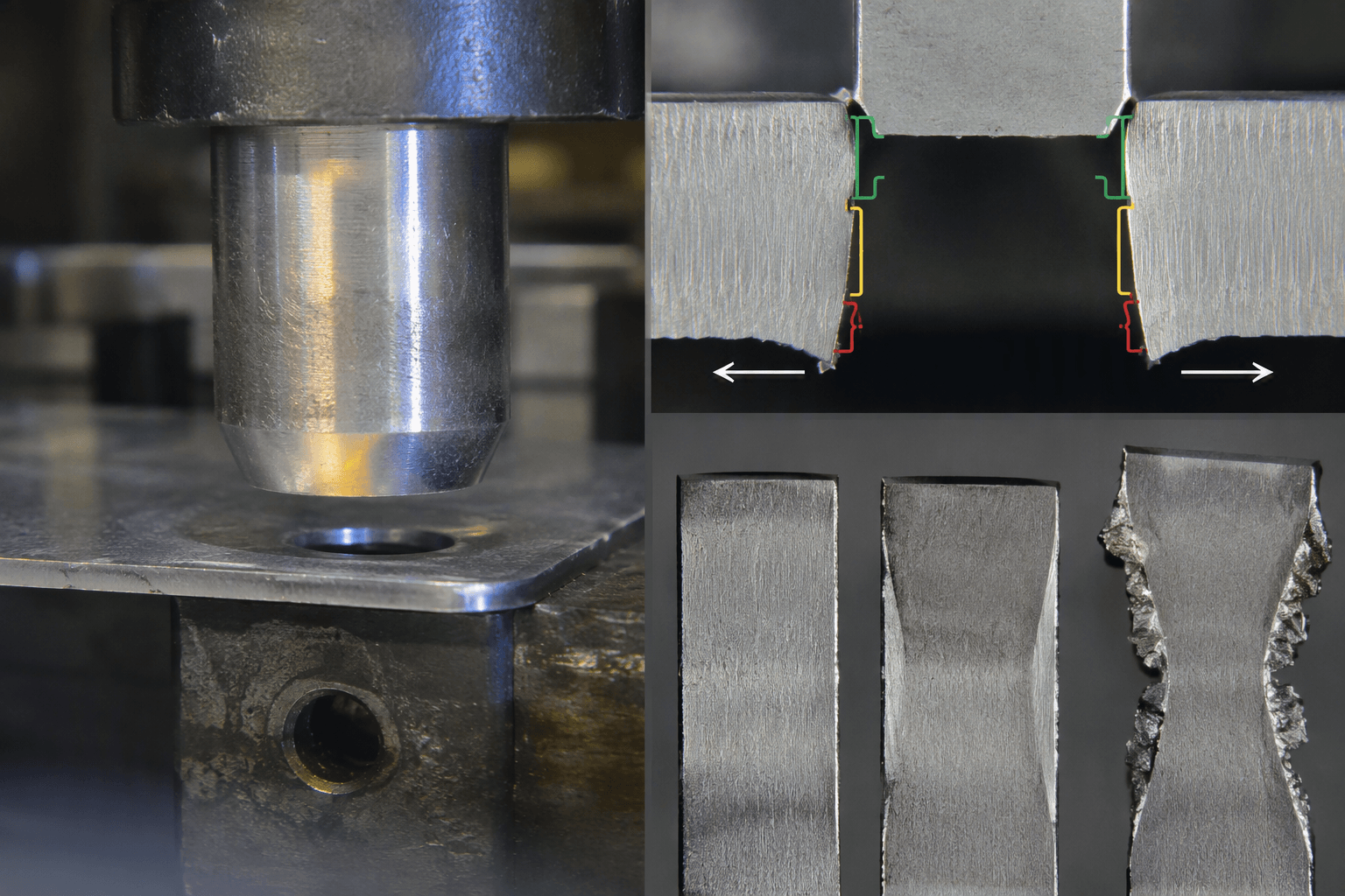
Punching places a punch over a die opening and drives it through the sheet. The material first deforms and is penetrated near the cutting edges. Fracture zones then develop from the punch and die edges until the remaining section separates. In ordinary piercing, the slug is usually waste or is collected for recycling. In blanking, the separated blank may instead be the useful part.
- Alignment: the punch is positioned over the die opening and the sheet is supported.
- Penetration: the punch edge enters the sheet and starts the shearing zone.
- Fracture: cracks grow from the punch and die edges until the remaining section separates.
- Separation: the slug exits toward the die side, leaving a cut edge and normally a burr on the fracture-exit side.
CNC turret punching uses programmed positioning and tool selection to produce repeated holes, slots, louvers, and cutouts without requiring a dedicated die for every part. The available tool shapes, indexing arrangements, material support, and forming options still limit the geometry. Some punch systems can create a louver, dimple, or countersink with a forming tool, but that feature should be identified as a forming operation rather than assumed to be ordinary hole punching.
Punch-die clearance is central to the result. The suitable clearance depends on the alloy, thickness, strength, punch size, die design, and machine setup. An unsuitable gap or a worn or damaged tool can increase burrs, alter the opening dimension, roughen the edge, and contribute to local distortion. The drawing should therefore define the functional edge condition and inspection expectation instead of simply requesting a punched hole.
Punching primarily changes the sheet locally through shearing. It does not automatically create the same three-dimensional geometry as bending, flanging, embossing, or drawing. If a part needs both openings and formed geometry, the route may be punching followed by bending or forming, with the operation order and datums considered together.
Match the route to the feature and production situation
Start with the required feature, then evaluate quantity, forecast, tooling, material, and quality risk. A flexible programmed route may suit a prototype or a design that changes frequently when the geometry is appropriate. Dedicated tooling may be considered for a recurring design when its investment, maintenance, storage, and revision assumptions are acceptable. There is no universal volume threshold or automatic cost winner.
| Required feature | Likely process family | Tooling implication | Principal quality checks |
|---|---|---|---|
| Flat holes or slots | CNC punching, or laser cutting where suitable | Confirm whether available tools cover the size and shape or whether special tooling is needed. | Hole size and position, burr, edge spacing, and local distortion |
| Repeated openings or cutout patterns | CNC punching or dedicated press tooling | Compare programmed flexibility with tooling investment, forecast stability, and revision frequency. | Pattern repeatability, flatness, material utilization, and tool condition |
| Complex two-dimensional profile | Laser cutting or programmed punching | Laser cutting can avoid dedicated punch tooling for some profiles; punching depends on suitable tools and part layout. | Profile dimensions, thermal edge effects where applicable, burr, and flatness |
| Flange, embossment, recess, or drawn section | Feature-specific press forming or another forming route | Confirm the die concept, forming stages, material suitability, and whether dedicated tooling is acceptable. | Radius, springback, formed height, cracks, wrinkles, and surface marking |
| Cutting combined with forming or bending | A planned sequence, such as punching followed by bending or forming | Define the operation order and datum scheme instead of selecting one machine by name. | Hole-to-form relationship, interference, distortion, and assembly fit |
Laser cutting is a thermal, non-press process. It can be relevant for some two-dimensional profiles, particularly when the design is changing or dedicated tooling is not justified. It still requires review of edge condition, heat effects, flatness, and any secondary work. Material grade, surface condition, strength, thickness, repeatability, existing tooling, prototype needs, annual demand, and tool amortization all influence the comparison.
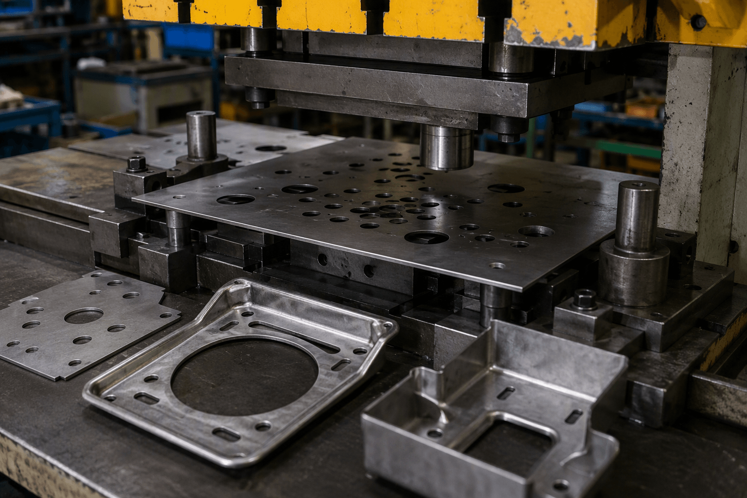
For products such as custom sheet metal enclosures, the practical answer is often a coordinated sequence: openings are cut, formed details are created where required, and panels are bent to establish assembly interfaces. Process selection should follow those interfaces, not the name of the machine used for one step.
DFM details that should be resolved on the drawing
Process fit should be checked before a drawing is released. A shape that looks simple in CAD can become difficult when openings are close to an edge, a formed feature is near a cut, or a tight flatness requirement conflicts with a dense hole pattern.
- Material and force: Grade, condition, thickness, tensile strength, and material direction affect both shearing and forming. Clearance, punch size, die geometry, and available machine force must be assessed together.
- Openings and webs: Hole diameter, slot width, hole-to-edge distance, spacing between openings, and narrow webs must be checked against the actual material and tooling. Do not apply one universal hole-to-thickness or edge-spacing rule.
- Burr and face orientation: The burr generally develops toward the fracture-exit side. State the permitted burr or edge condition, identify the functional or visible face, and specify whether deburring is required.
- Distortion and flatness: Dense holes, uneven material removal, small webs, and openings near a bend or formed edge can pull the sheet out of plane. Define flatness and whether flattening or straightening is permitted.
- Formed features: Specify bend or draw radii, corner geometry, formed height, springback expectations, forming sequence, and material-direction considerations. Holes close to a form may need relocation or a controlled sequence.
- Datums and tolerances: Use clear datums for hole position, profile dimensions, formed height, flatness, and mating interfaces. A general process name cannot replace functional requirements.
Hypothetical example 1: A perforated cover with a narrow strip between two rows of slots may need a spacing review before punching. If the web is too narrow for the selected material and clearance, the strip can distort even when each individual slot is correctly programmed.
Hypothetical example 2: On a custom metal bracket, a hole positioned close to a formed flange can be dimensionally correct in the flat blank but shift in relation to the flange after forming. The drawing should control the final mating relationship and inspection datum.
Information that makes a quotation meaningful
A supplier cannot validate manufacturability or price transparently from the words pressing and punching alone. The quotation request should provide enough information to compare CNC punching, dedicated press tooling, laser cutting, bending, or a combined sequence without hiding assumptions.
- Geometry pack: Send the current 2D drawing, 3D CAD file where available, revision status, material orientation, and all hole, slot, cutout, bend, flange, embossment, or drawn-feature dimensions.
- Material: State the grade or alloy, material condition, sheet thickness, and applicable thickness tolerance. Include any surface or appearance condition that affects the process.
- Quantity plan: Separate prototype, initial batch, recurring lot, and annual forecast quantities. State whether design revisions are expected.
- Tooling policy: Say whether dedicated tooling is acceptable, must be avoided, or may be considered after process review. Ask who owns any approved tool and how revisions will be handled.
- Price structure: Request separate tooling or non-recurring cost, setup or changeover assumptions, piece price, and deburring, flattening, or other required secondary operations.
- Quality definition: Specify burr limits, edge condition, flatness, hole-position tolerance, formed-feature tolerance, visual requirements, inspection method, and required documentation. The quality-control requirements should match the part’s functional interfaces.
- Proposed route and timing: Ask the supplier to identify CNC punching, dedicated press tooling, laser cutting, bending, or the combined sequence. Separate tool-build timing, first-sample approval, and production timing instead of accepting one unqualified lead-time figure.
Request a technical process-fit review
If the process is not fixed, send the 2D drawing and available 3D CAD, material grade and condition, sheet thickness, prototype and batch quantities, formed-feature details, tolerances, burr and flatness requirements, and your position on dedicated tooling. Yishang can review whether CNC punching and bending suit the documented geometry, identify assumptions that need separate confirmation if dedicated press forming is required, and prepare a quotation based on explicit process, quantity, tooling, and quality inputs.
Frequently Asked Questions
Is punching a type of pressing?
In the broad sense of pressworking, yes: punching can be performed with a press, and some suppliers include piercing and blanking under pressing or stamping. In practical communication, however, punching identifies a shearing operation that creates an opening, while pressing often refers to forming or stamping. Confirm the feature and operation instead of relying on the umbrella term.
Can pressing make holes?
It can if pressing is being used as a broad term for work performed with a press. The specific hole-making operation is normally called punching or piercing. A forming operation such as embossing or drawing changes the sheet shape but does not, by itself, describe the creation of a conventional hole.
Is CNC punching suitable for low-volume prototypes?
It can be suitable when the material, thickness, feature sizes, tool availability, and programmed geometry fit the process. For some prototypes, laser cutting may be a useful non-press alternative. The comparison should include edge condition, burr, flatness, repeatability, existing tooling, and whether the part also needs bending or forming; no single route fits every prototype.
Why do punched holes develop burrs or distortion?
Common contributors include unsuitable punch-die clearance, tool wear or damage, material strength that is not suited to the setup, small hole-to-edge distance, narrow webs, and dense or asymmetrical hole patterns. Control the result by specifying burr direction and limit, functional face, edge treatment, flatness, hole position, and the inspection method on the drawing or purchase specification.
If your drawing does not yet fix the process, request a drawing-based review before RFQ release. Share the geometry, material and thickness, prototype and production quantities, tooling preference, and hole, formed-feature, burr, flatness, and inspection requirements so the proposed route and quotation assumptions can be evaluated together.