
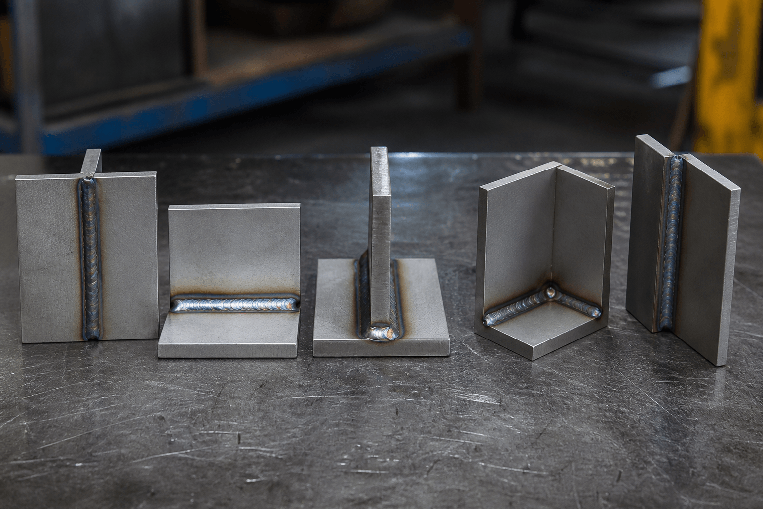
The five basic types of weld joints are butt, lap, tee, corner, and edge joints. For an OEM drawing of a cabinet, bracket, frame, or cover, identify this member geometry before choosing a weld detail. It determines where the edges, faces, and access paths are located. Fillet and groove describe weld geometry, while MIG, TIG, and manual arc describe welding processes. They are not alternative names for the five configurations.
For sheet-metal parts, selection depends on load direction, material and thickness, fit-up, access, appearance, distortion control, inspection, and production repeatability. The joint name alone does not establish weld size, penetration, structural capacity, leak tightness, or acceptance.
Five Basic Joint Configurations at a Glance
If a buyer sends a flat-pattern assembly or a 3D model for quotation, the first fabrication question is how the members meet before welding. That relationship affects edge preparation, fixture contact, visible surfaces, inspection access, and the risk of dimensional movement. The cross-sections below are conceptual and are not drawn to scale.
| Joint configuration | How the members meet | Typical sheet-metal considerations |
|---|---|---|
| Butt joint | Two edges meet in approximately the same plane. | Alignment, edge preparation, root-gap control, access, flushness, and distortion. |
| Lap joint | One member overlaps the face of another. | Overlap, concealed gaps, added material, edge access, and interface inspection. |
| Tee joint | One member meets the face of another at roughly a right angle. | Squareness, fixture location, fillet access, panel distortion, and welding from one or both sides. |
| Corner joint | Members meet at their edges to form an inside or outside angle. | Open or closed corners, visible surfaces, interior access, squareness, and dressing. |
| Edge joint | Adjacent edges of approximately parallel members are joined. | Edge support, heat concentration, intended load path, weld access, and inspection visibility. |
Butt     ─────────││─────────  edges in one plane
Lap      ────────────────────  upper member
                    ─────────  lower member overlaps
Tee                 │
             ───────┴────────  member meets panel face
Corner   ───────────┐
                    │          members meet at an angle
Edge     ═══════════╪════════  adjacent parallel edges
                    ╪
═══════════╪════════A butt joint may use square edges or a prepared groove. A corner joint may be open or closed, and a tee joint may use two separate pieces or a formed sheet-metal part. An edge joint is not simply a butt joint near an outside edge; its members are generally parallel or nearly parallel, with adjacent edges joined along the seam.
A Joint Configuration Is Not a Weld Type
When an OEM drawing identifies a tee, lap, or corner relationship, it has described the position of the members, not the complete weld requirement. For design review and quoting, keep three decisions separate: the member relationship, the deposited weld geometry, and the process used to produce it.
- Member relationship: butt, lap, tee, corner, and edge describe how the parts are arranged.
- Weld geometry: fillet and groove describe the cross-section and location of deposited weld metal.
- Welding process: MIG, TIG, and manual arc describe how heat and filler metal are applied.
TEE CONFIGURATION + FILLET       BUTT CONFIGURATION + GROOVE
          │                                  ╲   ╱
          │                                   ╲ ╱
──────────┴────────── panel             ──────┴────── members
       ▲ triangular fillet                 ▲ weld fills groove
A fillet weld has a roughly triangular profile and may be used on tee, corner, or lap configurations. A groove weld fills an opening between member edges; a butt joint may use a square-butt arrangement or a prepared groove when the design requires it. Tee and corner configurations can also use a designed groove.
Plug and slot welds can join overlapping sheet members through openings in one member, but they are weld forms rather than additional basic joint configurations. Process parameters, weld size, penetration, and weld length must be defined from the material, thickness, drawing, and approved project procedure—not inferred from the joint name.
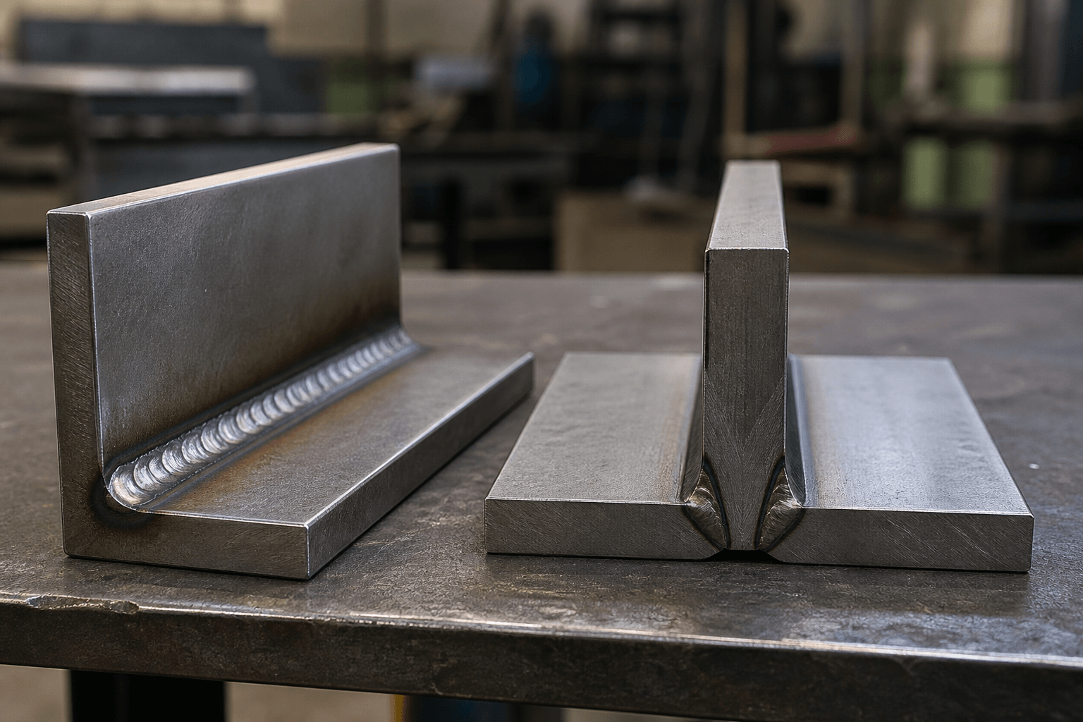
Types of Weld Joints: A Selection Matrix for Custom Sheet-Metal Assemblies
Start with the member relationship
When an engineer compares a bracket, enclosure, or frame detail, the useful question is not which joint is universally best. Compare each configuration against the load path, finished envelope, access, fit-up, fixture strategy, inspection visibility, material use, and expected production requirements.
| Configuration | Possible sheet-metal application | Design and production questions |
|---|---|---|
| Butt joint | End-to-end panels, covers, or transitions requiring a continuous plane. | Can the edges stay aligned? Is a flush face important? Is edge preparation or access to both sides required? |
| Lap joint | Brackets, straps, patches, covers, and overlapping enclosure panels. | Does the overlap provide seating and access without an unwanted step or concealed gap? Can the interface be inspected and cleaned? |
| Tee joint | Stiffeners, dividers, brackets, supports, and frame members on a panel face. | How will the upright locate? Is one-sided welding adequate for the design? How will heat affect flatness and squareness? |
| Corner joint | Boxes, cabinets, trays, frames, and parts meeting around an angle. | Is the corner open or closed? Which surfaces are visible? Can the inside or outside be reached, dressed, and inspected? |
| Edge joint | Flanges, covers, and edge seams where adjacent edges can be joined. | Will the edge support the specified requirement? How will heat concentrate at the edge, and can the completed seam be checked? |
Compare load path, access, and appearance
Load path: Review whether the joint transfers tension, shear, bending, or peel, and whether an eccentric bracket introduces leverage into the panel. Capacity must be evaluated with the member thickness, weld cross-section, weld length, stress concentration, and any fatigue or leak requirement. That review should be tied to the actual part geometry and specified weld detail.
Appearance and access: A butt joint may suit a flush visible face when the required alignment and preparation are achievable. A lap joint provides a seating region but can create a step or concealed interface. A tee joint suits many bracket and stiffener relationships, while a corner joint must account for both sides of a box or cabinet. An edge joint depends on adequate edge support and a workable inspection view.
Check material and production constraints
Material and production: Material grade, sheet thickness, and dissimilar-metal combinations affect heat response, filler selection, preparation, and procedure review. Thin sheet is more sensitive to gap variation, burn-through, and distortion, but that does not create one universal best configuration. A bent flange can create a tee or corner relationship from one part; bending tolerances still need to be coordinated with the welding detail.
For the wider sequence from cut preparation through welding and assembly, see custom sheet-metal fabrication for welded parts. Enclosures require particular attention to corner access and visible seams; see custom sheet-metal enclosures. Frames and supports also depend on squareness and mating interfaces, as discussed with welded metal frames.
DFM Details That Control Fit-Up, Distortion, and Dressing
Resolve fit-up, access, and inspection
After the configuration is selected, the drawing and fixture details determine whether the joint can be produced consistently. Resolve these points before release; welding should not be expected to correct poor preparation, uncontrolled gaps, or forced alignment.
| Detail | DFM review |
|---|---|
| Overlap and seating | Define the intended overlap, contact condition, and accessible weld area. Avoid an accidental pocket or hidden gap that complicates inspection, cleaning, or assembly. |
| Edge preparation and root gap | State the required edge condition and root-gap intent. Control them according to the material, thickness, design, and approved procedure rather than a generic dimension. |
| Weld size and length | Specify the design requirement and continuous or intermittent intent where applicable. Excess weld metal adds heat and dressing work; an underspecified joint leaves a critical assumption unresolved. |
| Access and inspection | Check the torch or electrode path, working angle, internal corners, enclosed areas, and line of sight for visual inspection. Assembly access is not necessarily welding access. |
| Fixtures and tacks | Place fixture contacts from drawing datums without blocking welding or inspection. Clamping and tack locations should hold the geometry without forcing a poor fit. |
| Sequence and heat | Review weld length, tack order, restraint, and welding sequence together. Shrinkage can affect flatness, squareness, holes, and assembly interfaces. |
| Grinding allowance | If a visible surface must be flush or uniform, define the dressing limit and allow suitable access. Grinding should not remove excessive parent material or compensate for incorrect fit-up. |
Control heat, sequence, and dressing
Upstream preparation also matters. Laser cutting or CNC punching can affect burrs, edge quality, holes, and slots that control seating or location. A bent flange requires review of bend angle, flange position, and springback before it establishes a tee or corner relationship. These preparation and forming operations are separate from welding; post-weld dressing, assembly, and inspection are separate downstream controls.
HYPOTHETICAL DFM SCENARIO: VISIBLE OUTER FACE
──────────────────────── panel
        ↑ dressing allowance only if specified
        └──────┐
               │ bracket
        ●      │ fixture contact outside the weld path
→ torch or electrode accessUse symptoms to direct a technical review:
- Burn-through: check thickness, gap variation, edge condition, heat concentration, and the approved process window.
- Inconsistent gaps: check cutting or bending variation, burrs, datums, seating, and fixture repeatability.
- Distortion: check restraint, tack placement, sequence, heat concentration, and tolerance stack-up.
- Lack of fusion: review fit-up, edge preparation, access, material condition, and the approved procedure.
- Excessive grinding: compare the weld profile with the specified size, visible-surface requirement, and dressing allowance.
These are troubleshooting prompts, not universal acceptance rules. Final disposition should follow the project requirements and the responsible welding or quality review.
What an OEM Drawing or RFQ Should Define
A drawing that names only a butt, lap, tee, corner, or edge joint identifies member geometry but not the complete fabrication requirement. For a useful quotation and manufacturability review, define the weld, finished dimensions, inspection expectations, and interfaces that the supplier must protect.
- Material: part number and revision, material grade, sheet thickness, condition where relevant, and any dissimilar-metal interface.
- Joint locations: configuration at each weld, with sections or enlarged details for crowded areas, internal corners, and concealed seams.
- Weld description: weld symbols or plain-language details identifying the weld side, weld type, location, and intended path.
- Weld requirements: weld size, effective penetration or performance requirement, weld length, and continuous or intermittent intent where applicable.
- Fit-up intent: edge preparation, root-gap intent, overlap, seating, and which details are drawing-controlled or procedure-controlled.
- Finished geometry: overall and local tolerances, flatness, squareness, hole or insert locations, and post-weld assembly interfaces.
- Surface and hardware protection: visible-surface expectations, grinding or dressing limits, and protection for threaded holes, inserts, mating faces, or installed hardware.
- Inspection: project-specific visual, dimensional, leak, load, or non-destructive inspection requirements and required records.
- Planning: prototype and production quantities, packaging or assembly needs, and the target assembly date.
Acceptance criteria and any governing code must come from the project specification or approved procedure. A generic article cannot define universal weld sizes, current or voltage settings, inspection levels, or acceptance limits. Inspection planning can be coordinated with quality control and inspection for custom metal products.
Frequently Asked Questions
What types of weld joints details should buyers define before requesting a quote?
Buyers should define the functional requirement, drawing notes, critical dimensions, material or process expectations, and any inspection points related to types of weld joints. This helps suppliers quote the same manufacturing scope instead of making different assumptions.
How can RFQ details affect cost, fit, or lead time?
RFQ details can change tooling, forming, welding, finishing, inspection, or rework requirements. If buyers do not clarify it early, two supplier quotes may look comparable while covering different production risks.
Why should drawing requirements be reviewed before prototype approval?
drawing requirements may look acceptable on a single sample but become harder to control during batch production. Buyers should confirm whether the prototype reflects the same process, finish, and inspection conditions expected for production.
What inspection points matter most for types of weld joints projects?
Important inspection points usually include fit-critical dimensions, holes or mating areas, cosmetic surfaces, finish build-up, welded or formed features, and any dimensions that affect downstream assembly. These points should appear in the RFQ or drawing notes.
How can buyers reduce prototype approval risk before batch production?
Buyers can reduce risk by clarifying drawings, locking key material and finish assumptions, defining inspection timing, approving a representative sample, and confirming which dimensions or surfaces require tighter process control.
How can Yishang help review types of weld joints requirements?
Yishang can review drawings, RFQ notes, material requirements, tolerance expectations, finish details, samples, and assembly needs to identify unclear assumptions before quoting or batch production.